____________________________________________________________________________________
____________________________________________________________________________________
Speeder X1 and X2 Configuration and API Guide
Page 30/36
No.
Type
Name / Description
Unit
Range
Default
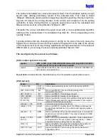
1
B
Operation Mode
Value
ASCII mode and Configuration mode
0
ASCII mode, continuous
1
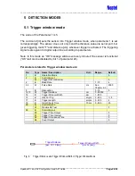
Triggering window mode
5
Speed measurement for vertical installation
7
Speed measurement for horizontal installation
12
2
B
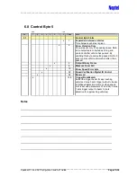
Control Byte 1 (See Chapter 6.4)
3
B
Control Byte 2 (See Chapter 6.5)
4
B
Baud Rate
1 = 1200 Bd
2 = 2400 Bd
3 = 4800 Bd
4 = 9600 Bd
5 = 19200 Bd
6 = 38400 Bd
7 = 57600 Bd
8 = 115200 Bd
9 = 230400 Bd
10 = 460800 Bd
11 = 921600 Bd
1 - 11
4
5,6
W
Pulse Rate
Laser pulsing rate
-
Averaging rate in Normal mode,
-
Vehicle detection in Speed
measurement and detection modes
Hz
50
– 2000
2000
7
B
Averaging
Average calculation of [2
n
] single shot
measurements to produce the final distance
value. E.g. n = 4 => Average = 16.
Note: Affects Normal mode only. Average
calculation affects the final measurement
speed. Sensor needs also some time interval
between every output of the result for serial
communication and internal operations, i.e. the
total result rate is a combination of parameter
settings and this interval.
2
n
0
– 14
4
8
B
Attenuation
The receiver sensitivity level can be attenuated
by this parameter.
Used for example with retro-reflectors.
0 = maximum sensitivity (natural targets),
15 = maximum attenuation (prisms)
0 - 15
0
9,10
W
Trigger Distance Beam B
Mode 7&5 (Chapter 4.1&5.1): Minimum
distance value for Beam B trigger window
Mode 12 (Chapter 0): Not user configurable.
Parameter has same meaning for Beam B as
par. 43 has for Beam A, see Chapter 4.3
cm
0 - 38000
11
B
Device Number
Sensors connected to the same serial port are
selected by the device number.
Command format is presented in chapter 1.2.
0 - 9
0

