10
4
Existing System Check
1.
Before beginning the install, ensure all hydraulic boom functions are operating properly on
the sprayer.
All Fold Functions
Main Lift Function
Wing Tilt Functions
Slant Function
2.
Inspect slide pads and wear surfaces for excessive wear. Replace or adjust if necessary.
3.
Ensure the boom guide-rods are set to the “tapered” position (factory setting).
4.
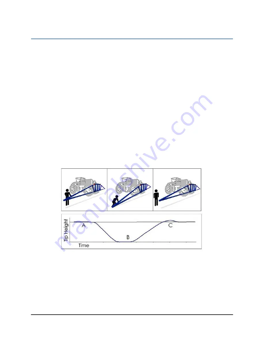
Set boom suspension to be critically damped (
Figure 5
). Adjust the boom damper
accordingly.
a.
Unlock the pendulum, and push boom tip down approximately 75 cm (30 inches).
b.
Hold the boom steady for a moment, and release.
c.
Ensure the boom returns to its relaxed state as quickly as possible, with little to no
overshoot.
Figure 5: Boom Push Test- Critically Damped
5.
Unfold the sprayer over a flat, unobstructed area (i.e. no power lines…etc.).
6.
Ensure all boom-fold operations are functional (place a check mark in boxes below).
7.
Bring engine to field-operational RPM and record.
Summary of Contents for UC4.5
Page 1: ...Hardi Aftermarket New Navigator New Commander Installation Manual HD7 HD12 ...
Page 6: ...3 3 Kit Parts 3 1 Kit Overview Figure 2 HD7 System Parts ...
Page 7: ...4 3 2 Hydraulic Plumbing Figure 3 Single Acting Force Boom Hydraulic Plumbing ...
Page 8: ...5 Figure 4 Double Acting Eagle Boom Hydraulic Plumbing ...
Page 22: ...19 Figure 17 Roll Sensors Mounted on an SPC Eagle Boom ...
Page 37: ...34 10 Cable Drawings 10 1 ITEM C03 44656D CABLE VALVE VARIABLE RATE DT ...
Page 38: ...35 10 2 ITEM C05 43210 20 CABLE UC5 NETWORK 18 AWG 20M ...
Page 39: ...36 10 3 ITEM C10 44650 51 CABLE UC4 5 POWER GENERIC PULL TYPE ...
Page 40: ...37 10 4 ITEM C11 44651 50 CABLE UC4 5 EXTENSION VALVE GENERIC ...
Page 41: ...38 10 5 ITEM C12 44658 42 CABLE UC4 INTERFACE AMP ML ONLY ...
Page 42: ...39 10 6 ITEM C13 44658 60 CABLE UC4 INTERFACE BYPASS AMP SUPERSEAL ...
Page 43: ...40 10 7 ITEM C16 44658 49 CABLE UC4 VALVE ROLL PIGTAIL ...
Page 44: ...41 10 8 ITEM C30 43250 06 CABLE UC5 BATTERY PIGTAIL FUSED ...


