21
8.4
Hydraulic Plumbing
From this point on in the installation the booms will be inoperative until the
hydraulics are fully installed.
1.
After the NORAC valve is mounted, the hydraulic hoses and fittings can be plumbed. The
plumbing for the hydraulic circuit is shown schematically in
Figure 3
.
2.
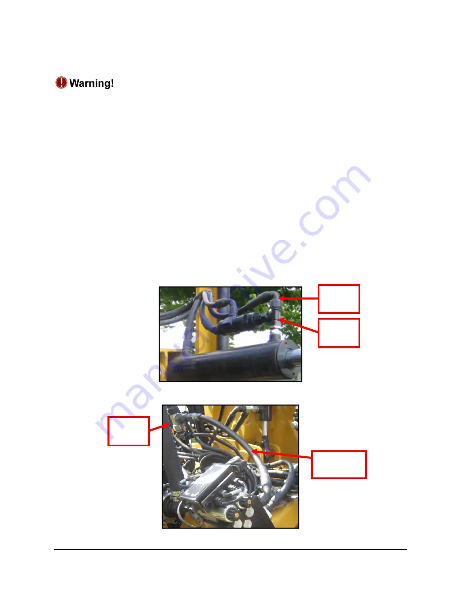
Disconnect the tilt “raise” lines from the sprayer boom cylinder and insert the two tees
(*F04) between the hoses and the valve block. Connect two hydraulic hoses (*H01) from
the free ends of the tees to the “B” ports on the NORAC valve block. Connect the 90
degree end of the hoses to the NORAC valve block.
3.
Disconnect the pressure and tank lines from the sprayer valve block and insert the two tees
(*F04) between the hoses and the valve block. Connect two hydraulic hoses (*H01) from
the free ends of the tees to the pressure and tank port on the NORAC valve block.
Connect the 90 degree end of the hoses to the NORAC valve block.
4.
There must be no other orifices in the hydraulic circuit between the NORAC valve block
and the tilt cylinders.
Figure 24: NORAC Line Tee’d in at Boom Cylinder
Figure 25: NORAC Tank Line Tee’d into Rogator Line
NORAC
Line
Tee
Fitting
Tee
Fitting
NORAC
Tank Line
Summary of Contents for UC5 Rogator 600
Page 1: ...Spray Height Controller Rogator 600 Installation Manual RG09 ...
Page 6: ...3 3 Kit Parts 3 1 Kit Overview Figure 2 RG09 System Parts ...
Page 7: ...4 3 2 Hydraulic Plumbing Figure 3 RG09 Hydraulic Plumbing ...
Page 11: ...8 Figure 7 Wing Sensor Bracket Mounting on Chafer Boom Outer Inner ...
Page 19: ...16 Figure 19 Input Module Mounting ...
Page 29: ...26 10 7 ITEM C20 43240 01 CABLE UC5 INTERFACE TILT DT ...
Page 30: ...27 10 8 ITEM C21 43240 31 CABLE UC5 INTERFACE MAIN DT WITH AUX 1 2 3 ...


