20
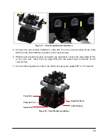
Figure 21: Valve Module Bracket Installation
5.
Connect the valve module CANbus to cable C01 from the control module. Route cable
C02 from the other CANbus connector to the input module.
6.
With the valve module securely mounted to the valve block, connect the valve cables (C10),
to the valve coils. Insert the 2-pin plugs (P01) into the unused 2-pin connectors on the
valve module.
7.
Connect the temperature probe to the valve block using the supplied 3/8” x 1/2” hex bolt.
Figure 22: Valve Module Installation
Tank Port
Pressure Port
Sense Port
Left Tilt Ports
Right Tilt Ports
Summary of Contents for UC5 Sx275
Page 1: ...Versatile Sx275 Installation Manual VS01 ...
Page 7: ...4 4 Kit Parts 4 1 Kit Overview Figure 2 VS01 System Parts ...
Page 8: ...5 4 2 Hydraulic Plumbing Figure 3 VS01 Hydraulic Plumbing ...
Page 33: ...30 12 7 ITEM C20 43240 01 CABLE UC5 INTERFACE TILT DT ...
Page 34: ...31 12 8 ITEM C21 43240 07 CABLE UC5 INTERFACE MAIN DT WITH AUX 1 2 ...
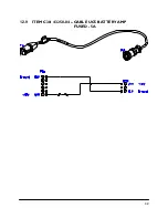
Page 35: ...32 12 9 ITEM C30 43250 04 CABLE UC5 BATTERY AMP FUSED 5A ...


