background image


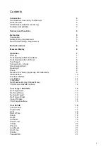
Contents


Introduction 

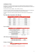
Part Numbers Covered by This Manual 

Parts Included 

USB Wireless Adapters (accessory) 

Software Compatibility 


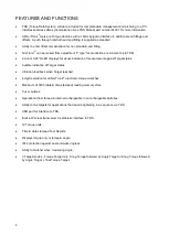
Features and Functions 


Before Use 

Preparation 

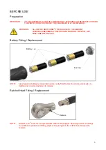
Battery Fitting / Replacement 

Ratchet Head Fitting / Replacement 


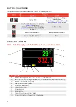
Button Functions 


Measure Display 


Operation 

Start Up 

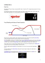
Peak Reading with Manual Reset 

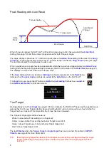
Peak Reading with Auto Reset 

Tool Target 

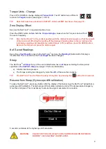
Torque Units – Change 

Zero Display Offset 

Reading # 

Sleep 

Resume from Sleep (Gyroscope drift calibration) 

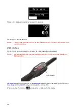
USB Interface 

10 

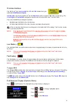
Wireless Interface 

11 

Low Battery 

11 

Flat Battery 

11 

Exit Measure Display (Options Menu) 

11 

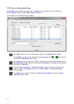
TDS Receive Results Interface 

12 


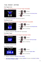
Tool Target - SETTING 

13 

Set Target Units 

13 

Set Snug Torque 

13 

Set Angle Target 

13 

Set Torque Target 

13 

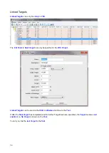
Linked Targets 

14 

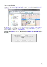
TDS Target Interface 

15 


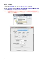
Tool SETUP 

16 

Torque Limits 

17 

Angle Limits 

17 

Units 

18 

Date & Time 

18 

Sleep 

19 

Angle 

19 

Auto Zero 

19 

Active From 

19 

Vibrate 

20 

Wireless 

20 

Auto Reset 

21 

Hold Time 

21 

Display 

21 

Torque CRS 

21 


Summary of Contents for NorTronic 43500

Page 1: ...ORBAR TORQUE TOOLS NZ LTD B3 269A Mt Smart Road Onehunga Auckland 1061 NEW ZEALAND Tel 64 9579 8653 Email nz norbar com au NORBAR TORQUE TOOLS PTE LTD 194 Pandan Loop 07 20 Pantech Business Hub SINGAPORE 128383 Tel 65 6841 1371 Email singapore norbar com au NORBAR TORQUE TOOLS SHANGHAI LTD E Building 5F no 1618 Yishan Road Minhang District Shanghai CHINA 201103 Tel 86 21 6145 0368 Email sales norb...

Page 2: ......

Page 3: ...get 8 Torque Units Change 9 Zero Display Offset 9 Reading 9 Sleep 9 Resume from Sleep Gyroscope drift calibration 9 USB Interface 10 Wireless Interface 11 Low Battery 11 Flat Battery 11 Exit Measure Display Options Menu 11 TDS Receive Results Interface 12 Tool Target SETTING 13 Set Target Units 13 Set Snug Torque 13 Set Angle Target 13 Set Torque Target 13 Linked Targets 14 TDS Target Interface 15...

Page 4: ...ew Results 22 Erase All 22 About 23 Specifications 24 Maintenance 25 NorTronic Calibration 25 Battery Replacement 25 Repair 25 Cleaning 25 Product Disposal 25 Battery Disposal 25 Trouble Shooting 26 Glossary of Terms 26 ...

Page 5: ...by This Manual Part Number Torque Capacity Ratchet Square Drive Wireless Communication Frequency 43500 50 N m 868 MHz 43501 50 N m 868 MHz 43502 200 N m 868 MHz 43503 330 N m 868 MHz 43504 50 N m 915 MHz 43505 50 N m 915 MHz 43506 200 N m 915 MHz 43507 330 N m 915 MHz Parts Included Parts Included Part Number Quantity NorTronic electronic torque wrench 4350X 1 USB flash drive Manuals Software 6113...

Page 6: ...urement against Target status Audible indication of Target status Vibration feedback when Target reached 4 digit resolution for all NorTronic electronic torque wrenches Maximum of 3000 date time stamped reading memory store 5 user buttons Operational from three AA internal rechargeable non rechargeable batteries Ability to link targets for applications that require tightening in a sequence via TDS...

Page 7: ...TCHING ON WIPE OFF ANY MOISTURE BEFORE USE Battery Fitting Replacement NOTE Insert positive battery terminal into handle cavity first Rotate the end cap clockwise to tighten and counter clockwise to release Ratchet Head Fitting Replacement NOTE All NorTronic tools are Torque Handles with a 16mm spigot Should you wish to change to a different spanner end fitting depress the plunger on the ratchet h...

Page 8: ...ed to P C TDS 5 Low Battery Flat Battery 6 Current Torque Units 7 Torque reading 8 Angle reading 9 Current Snug Torque Angle Target 10 Torque CRS has been changed from default value Button Function Operation SETUP Change Units Scroll through options or change a selected value When changing a value hold the button down for a faster rate of change Zero Torque Angle display if below the Active From t...

Page 9: ...shown as 0 until the Torque is above the Active From setting for the tool If the Snug Torque value is set See page 13 and is above the Active From setting the Angle display is shown as 0 until the Torque reaches the Snug Torque value and then displays the Angle value in peak mode After a Peak Torque or Angle has been applied and then the Torque has dropped below the Active From setting both the To...

Page 10: ...ing detected the Torque Angle readings are saved to the Data Store on the NorTronic If a Target is in use press the UP button to delete the last reading that has been saved via the Delete Last Result confirmation screen Delete Last Result Y N Tool Target Having already set a Tool Target see page 13 for more details the NorTronic beeps as the applied torque approaches the Torque Target starting slo...

Page 11: ... NorTronic memory the Reading bottom left of display is incremented This is reset when the Tool Target has been changed Sleep The NorTronic will Sleep if any of the events listed below have not happened during the time period specified in Tool SETUP Sleep see page 19 for more information a A button has been pressed b The Torque reading has changed by more than 2 of the wrenches capacity TIP The No...

Page 12: ...erface The NorTronic can be connected to a PC with TDS installed using the cable supplied NOTE Remove the USB cover to access the USB connector The USB cover must be fitted for IP44 protection Test Results saved on the NorTronic to the Data Store will be copied to TDS when synchronising The Tool Target and Tool SETUP configuration can also be sent from TDS When connected the USB icon will appear o...

Page 13: ...attery The LOW BATTERY icon will be shown when there is approximately 20 minutes of operational life left in the NorTronic NOTE This icon will overwrite the Wireless or USB icons but the NorTronic will remain connected Flat Battery The Flat Battery icon will be shown for approximately 30 seconds before shutting down Further button presses will not wake up the tool The batteries must be removed and...

Page 14: ...ll change from to when the tool is connected to Receive Results in TDS After a peak has been detected press ZERO to send both the peak Torque Angle values to Receive Results in TDS If the tool is configured for Auto Reset the readings are automatically sent during the Hold Time The save button is inactive i e Test Results are NOT saved on the NorTronic When the button is pressed Test Results will ...

Page 15: ... the Set Angle Target The button is not functional Minimum 0 Maximum 100 of NorTronic Torque capacity Set Angle Target NOTE This screen will not be shown if Angle is Not Enabled in SETUP Set Angle 32 Press or to change Press to confirm and go to Set Torque Target The button is not functional Minimum 0 Maximum 999 Set Torque Target Set Target N m 298 4 Press or to change Press to confirm and go to ...

Page 16: ...e specified in the TDS Target Linked Targets can be sent via the USB or Wireless interface to the Tool If after the final Target has completed and No further Target has been specified the Target becomes not enabled i e No Target is shown on the Tool To carry on link the last Target to the first ...

Page 17: ... can be changed on the tool unless the Locked option has been ticked in Set Tool Options and downloaded to the NorTronic by clicking the Update button on Set Tool Options as shown below See page 16 for more information on Set Tool Options The Locked option disables the NorTronic user from altering the Target SETTING and Tool SETUP on the NorTronic ...

Page 18: ...udes Limits Units Time Date Sleep Angle Display Auto Zero Active From Vibrate Wireless Auto Reset Display and Torque Centres NOTE Tool SETUP is active unless the Lock option has been ticked and downloaded to NorTronic via the TDS software This disables the NorTronic user from altering the Tool SETUP or Target SETTING ...

Page 19: ...nge highlighted value Press to confirm and go to LO Limit Press to exit to SETUP saving changes of Torque Target setting Minimum 0 Maximum 20 Default 4 Angle Limits Angle HI Limit 4 LO Limit 4 Press or to change highlighted value Press to confirm and go to LO Limit Press to exit to SETUP saving changes Target HI Limit Target LO Limit in degrees Minimum 0 Maximum 20 Default 4 NOTE Tool SETUP is a s...

Page 20: ... or to highlight unit Press to enable green or disable red Press to confirm and exit to SETUP saving changes Minimum Enabled 1 Maximum Enabled All 12 Default All 12 Date Time Date Time 24 01 14 16 05 14 Press or to change highlighted value Press or to confirm and step onto next change month year hours minutes seconds 24 hour clock format The Time Date will always be checked and updated when synchr...

Page 21: ...to change setting Press or to confirm and exit to SETUP Enabled Display Torque Angle Not Enabled Display Torque only Auto Zero Auto Zero Enabled Press or to change setting Press or to confirm and exit to SETUP Enabled both the TORQUE ANGLE readings will Auto Zero on power up or resume from sleep Not Enabled the user must press the ZERO button to reset the Torque display to the current Torque input...

Page 22: ... Enabled Wireless communication is Not Active Wireless Enabled Node 2 868 MHz Press or to change value Press to confirm and go to 868 915 MHz Press to confirm and exit to SETUP saving changes A Node number is an individual identification of a tool on the wireless network If multiple NorTronic tools are communicating with the same USB wireless adapter at the same time they must each have individual...

Page 23: ... 0 Hold Time Hold Time 4Sec Press or to change value Press or to confirm and go to SETUP saving changes Minimum 1 Maximum 10 Default 4 Display Inverse Not Enabled Press or to change value Press or to confirm and go to SETUP saving changes Enabled Black digits on White background Not Enabled White digits on Black background when in the Measure display WARNING WHITE DIGITS ON BLACK BACKGROUND WILL R...

Page 24: ...334 6 N m 93 Press the or buttons to scroll through the Saved Test Results screen s Press the button on to exit back to Data Store Result 30 03 12 10 48 23 360 5 N m 101 Erase All Delete Results Y N Press or to change highlighted option Press to confirm Press to go to SETUP WARNING SAVED TEST RESULTS CANNOT BE RETRIEVED FROM THE TOOL ONCE THEY HAVE BEEN DELETED ...

Page 25: ...ch of the 3 screens starting with serial is displayed for 2 seconds before returning to SETUP Tool Identification SERIAL 2012 123456 MODEL 4350X Version Version 1 XX Hardware options fitted Options Wireless Angle ...

Page 26: ...t NiMH Nickel metal Hydride Coin cell Renata 36 mAh CR1220 Materials finish Handle Powder coated aluminium Body tube Xylan coated steel Lever arm Nickel plated steel Ratchet head Chrome plated steel Battery cap polished stainless steel Environmental protection IP44 Electromagnetic Compatibility In conformance with EN 61326 2006 EMC Directive USB 2 0 Device 5 pin mini Wireless Transceiver 868 MHz c...

Page 27: ...bar or by a Norbar approved agent where all the facilities to ensure the NorTronic is functioning at maximum accuracy are available Cleaning Do not use abrasives or solvent based cleaners Product Disposal This symbol on the product indicates that it must not be disposed of in the general waste Please dispose of according to your local recycling laws and regulations Contact your distributor or see ...

Page 28: ...e Frequency of beep does not get faster when approaching a Target Apply the torque slower GLOSSARY OF TERMS Word or Term Meaning Number Active From Value from which the memory modes operate Capacity NorTronic full scale CRS Centres Frequency Response Frequency value below which signals are passed Hold Time The length of time a reading is displayed until automatically reset Hz Hertz unit of frequen...

Reviews: