background image


MITX-6891   

Mini-ITX Motherboard Based on Intel G45 Chipset


43

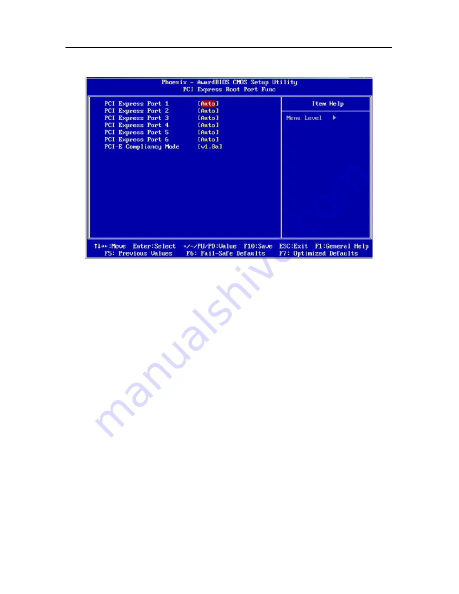
PCI Express Root Port Func 


PCI Express port 1-6 

Set whether use PCI-E 1-6 port. The choices:<Auto(default)>

<Disabled>

<Enabled>. 


PCI-E Compliancy Mode 

This option allows you to choose the PCI-E Compliancy Mode. The choices

<v1.0a 

(default)>

<v1.0>. 


VGA Setting 

PEG/Onchip VGA Control


This item is setting for start up video output from an add-on-card or onboard device. The 

choices

<Onchip VGA>, <PEG Port>, <Auto>. 


PEG Force X1 

PCI Express Graphics port transmission speed setting 

<Enabled>:×1 mode,   

<Disabled>: default 


On-Chip Frame Buffer Size 

This item allows the user to adjust on-chip graphics of memory buffer. The choices

<1MB>

<8MB(default)>. 

Summary of Contents for MITX-6891

Page 1: ...r J1 J2 J3 J4 14 2 6 External Connector 15 2 6 1 SATA Connector SATA1 SATA2 15 2 6 2 Serial port COM 16 2 6 3 Display Connector DVIB DVIC 16 2 6 4 USB Ethernet ports USB LAN_USB USB1 3 19 2 6 5 LAN LED LAN_LED 21 2 6 6 Keyboard and Mouse port PS 2 21 2 6 7 IRDA interface IRDA 23 2 6 8 GPIO GPIO 24 2 6 9 Power Supply Connectors ATX PWR 25 2 6 10 Fan Socket CPUFAN1 CPUFAN2 SYS_FAN 26 2 6 11 Audio Po...

Page 2: ... Super IO Device 47 3 4 3 USB Device Setting 48 3 5 Power Management Setup 49 3 6 PnP PCI Configurations 53 3 7 PC Health Status 55 3 8 Load Fail Safe Defaults 56 3 9 Load Optimized Defaults 57 3 10 Set Supervisor Password 57 3 11 Set User Password 58 3 12 Save Exit Setup 58 3 13 Exit Without Saving 59 Appendix 60 Appendix 1 Driver Installation 60 Appendix 2 Watchdog programmer guide 61 Appendix3 ...

Page 3: ...check your package completely as the following item checklist first if you find any components lost or damaged please contact your retailer MITX 6891 motherboard User s Manual Drive Disk SATA Data Cable Serial port converts cable Jumpers 1pcs 1pcs 1pcs 2pcs 1pcs 4pcs ...

Page 4: ...Chapter 1 General Information ...

Page 5: ... support 10 100 1000 Mbps self adaptive Provide two SATA seven Ⅱ USB2 0 one COM etc MITX 6891 is an integrated powerful computing platform with standard digital input out ports Mini PCI E slot IrDA Watchdog Timer It is specially suitable for POS kiosk ATM and Rail Transportation applications 1 2 Specifications Configuration Standard Mini ITX Standard motherboard Dimensions 170mm X 170mm L W Proces...

Page 6: ... bandwidth can reach up to 12 8GB s in dual channel model Ⅲ Supporting DDR 1066 Ⅲ MHz its bandwidth can reach up to 17GB s in dual channel model Storage 2x Serial ATAⅡ Ports The transfer speed is up to 300MB s LAN Chipset Marvell PCIe Gigabit PHY 88E8075 Supports WOL PXE DASH technology 1x GbE PCIE_1X NIC Support 10 100 1000 Mbps adapting 1x RJ45 port Audio Chipset ALC888 Audio Controller Supports...

Page 7: ...ort support RS232 Norma PS 2 keyboard and mouse port 1x IrDA port Programmable input output interfaces 2x6Pin 6input 6output Power Supply 12V plug Standard ATX PowerSupply Watchdog Support H W reset function BIOS 8MB SPI Flash BIOS Support ACPI Power manage Environmental Operate Temp 0 60 Storage Temp 40 85 Operating Humidity 5 95 ...

Page 8: ...Chapter 2 Installation Instructions ...

Page 9: ...ng picture is interface index for MITX 6891 when you install your devices please consult it and read the following guide During installation please care for some devices if incorrectly install it will not work normally Notice During installation in order to protect the part of board please put on antistatic gloves MITX 6891 Connectors Locations ...

Page 10: ... MITX 6891 per this manual 2 Installing System memory 3 Installing CPU and CPUFAN 4 Connect all of the signal line cable panel control circuitry and power supply 5 Finish BIOS setup Key components of this motherboard are Integrated circuit and these components will be easily damaged by electrostatic influence So before installing motherboard you should always follow the following precautions ...

Page 11: ... the notch on the DIMM matches the break on the socket 3 Firmly insert the DIMM into the socket until the retaining clips snap back in place and the DIMM is properly seated IMPORTANT A DDRⅢ DIMM is keyed with a notch so that it fits in only one direction Do not force a DIMM into a socket to avoid damaging the DIMM The DDRⅢ DIMM sockets do not support DDR DDRⅡ DIMMs Do not install DDR DDRⅡ DIMMs to...

Page 12: ...lication have been set when them leave factory can not be changed 2 4 1 Installing the CPU To install a CPU 1 Locate the CPU socket on the motherboard 2 Press the load lever with your thumb A then move it to the left B until it is released from the retention tab NOTE To prevent damage to the socket pins do not remove the PnP cap unless you are installing a CPU 3 Lift the load lever in the directio...

Page 13: ...n the CPU over the socket making sure that the gold triangle is on the bottom left corner of the socket then fit the socket alignment key into the CPU notch NOTE The CPU fits in only one correct orientation DO NOT force the CPU into the socket to prevent bending the connectors on the socket and damaging the CPU 6 Close the load plate A then push the load lever B until it snaps into the retention t...

Page 14: ...fasteners at a time in a diagonal sequence to secure the heatsink and fan assembly in place 3 Connect the CPU fan cable to the connector on the motherboard labeled CPU_FAN Do not forgets to connect the CPU fan connector Hardware monitoring errors can occur if you fail to plug this connector NOTE Before fixing daub coolant on the surface of the heat sink connect CPU first to swell the cooling funct...

Page 15: ...ll the CPU heatsink and fan 1 Disconnect the CPU fan cable from the connector on the motherboard 2 Rotate each fastener counterclockwise 3 Pull up two fasteners at a time in a diagonal sequence to disengage the heatsink and fan assembly from the motherboard 4 Carefully remove the heatsink and fan assembly from the motherboard ...

Page 16: ...oard Based on Intel G45 Chipset 11 5 Rotate each fastener clockwise to ensure correct orientation when reinstalling The narrow end of the groove should point outward after resetting The photo shows the groove shaded for emphasis ...

Page 17: ...sent pin1 pin2 connected and 2 3 to represent pin2 pin3 connected 2 5 1 Clear CMOS JCC This jumper is used to erase CMOS data and reset system BIOS information The procedure for clearing CMOS is 1 Turn off the system 2 Set JCC closed for just a few seconds 3 Turn on the system The BIOS is now reset to its default setting 4 Save exit setup setting JCC Close Clear CMOS BIOS renew to initialization O...

Page 18: ...ard is contained in the Flash ROM If the jumper JAV1 is set as dosed you will be unable to flash the BIOS However in this status the system BIOS is protected from being attacked by serious virus such CIH virus Setting JAV Open Enable to flash BIOS Close Disable to flash BIOS default ...

Page 19: ...2 When the J1 J2 is set to 1 2 the bridge chip only DVIC 1 signal if connected to a display please take in the DVIC 1 When the J1 J2 is set to 2 3 the bridge chip only DVIC 2 signal if connected to a display please take in the DVIC 2 J3 J4 set by reference to J1 J2 J1 J2 J1 J2 Port Select 1 2 1 2 DVIC 1 1 2 2 3 DVIC 2 J3 J4 J3 J4 Port Select 1 2 1 2 DVIB 1 1 2 2 3 DVIB 2 Remarks J1 and J2 J3 and J...

Page 20: ...refully read this manual when connecting external connector so as to avoid damage to the motherboard 2 6 1 SATA Connector SATA1 SATA2 The board provide 2 Serial ATAⅡ Ports The transfer speed is up to 300MB s SATA1 SATA2 Pin Pin Name 1 GND 2 SATA_TXP 3 SATA_TXN 4 GND 5 SATA_RXN 6 SATA_RXP 7 GND ...

Page 21: ...5 6 HCTS1 HDTR1 7 8 HRI1 GND 9 10 GND 2 6 3 Display Connector DVIB DVIC The board provides 3x DVI D output 1x DVI I DVI I DVIC 2 Signal can be convert to VGA signal Use the adaptor to change the standard DVI I interface to VGA interface DB15 DVI connector jumper settings please refer to 2 5 3 you can recognize them by location The DVIB 1and DVIC 1 is the jack near PCB and the DVIB 2and DVIC 2 is a...

Page 22: ...B 1 Pin Name Pin Pin Name D2 A 1 2 D2 A GND 3 4 NC NC 5 6 SC DDC_A SD DDC_A 7 8 NC D1 A 9 10 D1 A GND 11 12 NC NC 13 14 VCC5 GND 15 16 HDMI_PLUG_A D0 A 17 18 D0 A GND 19 20 NC NC 21 22 GND CLK A 23 24 CLK A GND 49 50 GND DVIB 2 Pin Name Pin Pin Name D2 B 25 26 D2 B ...

Page 23: ... NC NC 37 38 VCC5 GND 39 40 HDMI_PLUG_B D0 B 41 42 D0 B GND 43 44 NC NC 45 46 GND CLK B 47 48 CLK B GND 51 52 GND DVIC 1 Pin Name Pin Pin Name D2 C 1 2 D2 C GND 3 4 NC NC 5 6 SC DDC_C SD DDC_C 7 8 NC D1 C 9 10 D1 C GND 11 12 NC NC 13 14 VCC5 GND 15 16 HDMI_PLUG_C D0 C 17 18 D0 C GND 19 20 NC NC 21 22 GND CLK C 23 24 CLK C GND 49 50 GND ...

Page 24: ...3 44 NC NC 45 46 GND CLK D 47 48 CLK D GND 51 52 GND 2 6 4 USB Ethernet ports USB LAN_USB USB1 3 The board provides up to seven USB Ports One RJ45 Ethernet interface thereinto USB_RJ include 2x USB2 0 ports and 1x 10 100 1000Mb RJ45 Ethernet interface The board provides 3 group 1 x 5 pin header connectors USB_1 USB_2 USB_3 You will need an adapter cable if you use a standard USB connector Two LEDs...

Page 25: ... LILED state Network link status ACTLED Yellow state Message transfer status Green 100Mbps On Orang 1000Mbps effective On transfering Off noneffective Off No message transfering Standard USB ports define Pin Name Pin 1 5V 2 USB DATA 3 USB DATA 4 GND USB1 USB2 USB3ports define Pin Name Pin 1 5V ...

Page 26: ...ntel G45 Chipset 21 2 USB DATA 3 USB DATA 4 GND 5 GND 2 6 5 LAN LED LAN_LED Pin Name Pin Pin Name WAN 1 2 VCC3SB PAN 3 4 VCC3SB LAN 5 6 VCC3SB 2 6 6 Keyboard and Mouse port PS 2 Two PS 2 ports for KB MS Green for Mouse and Purple for Keyboard ...

Page 27: ...MITX 6891 Mini ITX Motherboard Based on Intel G45 Chipset 22 Mouse Pin Name Pin 7 5V 8 GND 9 NC 10 MS_DAT A 11 MS_CLK 12 NC Keyboard Pin Pin Name 1 5V 2 GND 3 NC 4 KB_DATA 5 KB_CLK 6 NC ...

Page 28: ...Based on Intel G45 Chipset 23 2 6 7 IRDA interface IRDA This board provides a group of IrDA pins supports IrDA version1 0 SIR or SHARP ASK IR protocol infrared ray data transmission function Pin Pin Name 1 5V 2 NC 3 IRRX 4 GND 5 IRTX ...

Page 29: ...O connector The 12 digital input output can be programmed to read or control devices with input or output defined The default setting is 6 bits input and 6 bits output GPIO Pin Name Pin Pin Name GPIN_1 1 2 GPOUT_1 GPIN_2 3 4 GPOUT_2 GPIN_3 5 6 GPOUT_3 GPIN_4 7 8 GPOUT_4 GPIN_5 9 10 GPOUT_5 GPIN_6 GPIO_VCC 11 12 GPOUT_6 GND ...

Page 30: ...ectors ATX PWR ATX Power supply 20PIN Special power supplies with 12V plug ATX Pin Name Pin Pin Name 3 3V 11 1 3 3V 12V 12 2 3 3V GND 13 3 GND PS ON 14 4 5V GND 15 5 GND GND 16 6 5V GND 17 7 GND 5V 18 8 PW OK 5V 19 9 5V SB 5V 20 10 12V PWR Pin Name Pin Pin Name 12V 3 1 GND 12V 4 2 GND ...

Page 31: ...an 350mA 4 2W 12V 2 Please ensure that the fan wire is consistent with the wire for this socket The power cord must be in the middle position In addition ensure the GND cord wire usually black and fan rotation output pulse signal wire in other color It is recommended that the fan with rotary speed detection be used CPUFAN1 CPUFAN2 Pin Pin Name 1 GND 2 12V 3 Speed Detect 4 Speed Control SYS_FAN Pin...

Page 32: ...ecognize them by location The MIC IN is the jack near PCB and the SPEAKER OUT is at the far end of PCB or color Red is MIC IN and green is SPEAKER OUT The board provides one group 2x5Pin audio connector You will need an adapter cable if you use a standard audio connector J5 Pin Name Pin Pin Name GND 1 2 MIC R FRON L 3 4 FRONT R GND 5 6 GND GND 7 8 GND LINE L 9 10 LINE R ...

Page 33: ...tor FRONT FRONT use to connect function button or LED on front panel Front Panel connector Pin define Pin Name Pin Pin Name VCC5 1 2 VCC5 GND 3 4 NC GND 5 6 NC KELOCK 7 8 SPK GND 9 10 VCC5 GND 11 12 SLEEPSW GND 13 14 PWRBTN VCC5 15 16 PWR_LED GND 17 18 RSTBTN ICH_SATA_LED_N 19 20 HDD_LED ...

Page 34: ...er switch on power LED on When system power switches off power LED off 2 Buzzer Pins pin 2 pin 8 for SPEAKER External Buzzer Pins for it have buzzer on this CPU card users can choose to connect external buzzer or not by yourself 3 KEYLOCK Pins pin7 pin9 for KEYLOCK Connecting keylock function control cable and these pins then it can carry out keylock function 4 Sleep key Pins pin11 pin12 for SLEEP...

Page 35: ...tem can not work on reset can make system restart without turning on off the power thereby it can prolong system serviceable life 8 IDE LED Pins pin19 pin20 for HDD LED As a rule there is a IDE LED on the panel of chassis while IDE device like hard Disk is reading or writing no matter which IDE device LED will flash shows that IDE device is running Connect IDE LED on chassis panel and these pins p...

Page 36: ...TX 6891 Mini ITX Motherboard Based on Intel G45 Chipset 31 2 6 14 Mini PCI E Slot Mini PCI E The back device of motherboard provides a mini PCI E slot the user can expand mini PCI E according to own need ...

Page 37: ...Chapter 3 BIOS Setup ...

Page 38: ...Example Awdflash 6891I100 bin P B C N X Remarks 1 Upgrading BISO may cause your system crash so please operate carefully 2 Please use the upgrading program in the CD ROM provided by us 3 Please do not power off or reboot the system when upgrading otherwise the BIOS maybe be damaged 4 Please backup your BIOS before upgrading Award BIOS Description Awards BIOS ROM has a built in setup program that a...

Page 39: ...at you see on your screen When the SETUP program starts you can see the CMOS Setup Utility Main screens are as follows Award BIOS on the map is the main menu Main Menu 11 set to provide the functions and two out of the way the user needs according to their own set of corresponding projects The following BIOS settings will be explained the various items 3 1 Standard CMOS Setup The CMOS RAM is power...

Page 40: ... user Time The times format in hour minute second base on the 24 hour time IDE Channel 0 1 Master Slave These 4 options are IDE HDD setting items Important Please select the right option for your IDE devices Please make sure that the specifications of the IDE devices are comply with the content of the device list If not the device will be fail In the main menu we have another auto detection functi...

Page 41: ...ary means the second IDE device and it refers to the IDE1 interface on the motherboard Every IDE device can have two IDE devices as Master Slave Video Select EGA or VGA display option item EGA VGA CGA 40 CGA 80 MONO Halt On The item determines whether the computer will stop if an error is detected during power up No Errors The system boot will not stop for any error All Errors Whenever the BIOS de...

Page 42: ...hermal When the temperature of CPU has reached the preset temperature by the factory the clock of the motherboard will be delayed The temperature device is activated and the detector inside the CPU is also activated to maintain the limit of temperature of CPU This can be set to 4 Min 8 Min 16 Min 32 Min Thermal Management ...

Page 43: ...lectively English Native Command Queuing Mode is overclocking mode PPM Mode SMM Mode is actually EIST and SMM Mode and Native Mode is EIST different models inside Native Mode But this is a relatively old overclocking mode only to the default SMM Mode replaced by Native Mode will be helpful for overclocking Intel SpeedStep technology option is EIST switch after the choice of open Native Mode better...

Page 44: ...kernel load dual processor in best way Enabled use multi kernel CPU Disabled use one of CPU 3 2 2 Removable Device Priority The above mentioned items are the order of boot devices can not be amendment 3 2 3 Hard Disk Boot Priority The above mentioned items are the order of boot devices can not be amendment ...

Page 45: ...m allows the user to Enabled default Disable CPU L3 cache Hyper Threading Technology This item allows the user to Enabled Disabled Hyper threading support for the Intel Pentium 4 processor with HT Technology The Choices Enabled default Disabled Quick Power On Self Test This option speeds up the Power On Self Test POST conducted as soon as the computer is turned on When enabled BIOS shortens or ski...

Page 46: ...kes repeat as determined by the keyboard controller The commands are Enabled or Disabled Enabling allows the typematic rate and delay to be selected Security Option This field allows you to limit access to the System and Setup The default value is Setup When you select System the system prompts for the User Password every time you boot up When you select Setup the system always boots up and prompt...

Page 47: ...floppy drive in the system If you set this feature to Disabled the BIOS will not report the missing floppy drive to Win95 98 Full Screen LOGO Show The splash screen can display the company LOGO Option Enabled Disabled Small Logo EPA Show The EPA logo appears at the right side of the monitor screen when the system is boot up The default setting is Enabled Summary Screen Show This item allows you to...

Page 48: ...prove performance certain space in memory can be reserved for ISA cards This memory must be mapped into the memory space below 16 MB The choices are Enabled and Disabled VT d Virtualization solutions enhanced by Intel VT allow a platform to run multiple operating systems OSs and applications as independent virtual machines allowing one computer system to function as multiple virtual systems For ex...

Page 49: ...e the PCI E Compliancy Mode The choices v1 0a default v1 0 VGA Setting PEG Onchip VGA Control This item is setting for start up video output from an add on card or onboard device The choices Onchip VGA PEG Port Auto PEG Force X1 PCI Express Graphics port transmission speed setting Enabled 1 mode Disabled default On Chip Frame Buffer Size This item allows the user to adjust on chip graphics of memo...

Page 50: ...Bios provides three options to choose DVMT FIXED and Both Total GFX Memory This item displays the total system memory size PAVP Mode The main protection against the high definition movie content playback the general set to Lite mode Boot Display The default setting is Auto Default The options available include Auto CRT LVDS CRT LVDS DVI CRT DVI CRT TV ...

Page 51: ...rals 3 4 1 OnChip IDE Device IDE HDD Block Mode You can enable the Primary IDE channel and or the Secondary IDE channel Any channel not enabled is disabled This field is for systems with only SCSI drives IDE DMA transfer access DMA transfer access The choices Disabled Enabled default ...

Page 52: ...aster Slave UDMA Ultra DMA 33 66 100 can be used when your IDE HDD support this kind of function In the meantime the OS includes a DMA driver Windows 95 OSR2 or third party IDE BUS control and driving programe If your HDD and your OS can support Ultra DMA 33 Ultra DMA 66 or Ultra DMA 100 Select Auto to enable BIOS support Options Auto Disabled On Chip Secondary PCI IDE Options Disabled Enabled SAT...

Page 53: ...PS 2 mice probably don t support this option The choices Button Only Keyboard 98 Hot Key Mouse Left Mouse Right KB Power ON Password If this is setted as Password in POWER ON Function you can use this to set the password for the booting of PS2 mouse Hot Key Power ON If this is setted as HotKey in POWER ON Function you can use this to set the hot key for PS 2 keyboard options are from CtrlF1 to Ctr...

Page 54: ...o IR Transmission Delay This item allows you to enable disable IR transmission delay The choices Enabled Disabled UR2 Duplex Mode This item allows you to select the IR half full duplex function The choices Half Full Use IR Pins Please refer to your IR equipment setting the correct signal TxD and RxD Option RxD2 TxD2 IR Rx2Tx2 3 4 3 USB Device Setting USB 1 0 Controller Select Enabled if your syste...

Page 55: ...lt in the support will automatically turn on when a high speed device is attached The choices are Enabled or Disabled USB Operation Mode Set the USB 2 0 controller to Hi Speed 480 Mbps or Full Speed 12 Mbps USB Keyboard Mouse Function Select Enabled if you plan to use a USB keyboard Mouse The choices are Enabled and Disabled USB Storage Function Select Enabled if you plan to use an external USB st...

Page 56: ...abled ACPI Function ACPI This is item to activate the ACPI function If you OS support ACPI aware For example Windows 98SE 2000 ME choice Enabled Option Enabled Disabled ACPI Suspend Type This item allows user to select sleep state when in suspend S1 POS The suspend mode is equivalent to a software power down S3 STR default The system shuts down with the exception of a refresh current to the system...

Page 57: ...ing Maximum power management Suspend Time Out 1 Min HDDPower Down 1Min Video Off Method This item allows user to determine the manner is which the monitor is blanked V H SYNC Blank This option will cause system to turn off vertical and horizontal synchronization ports and write blanks to the video buffer Blank Screen This option only writes blanks to the video buffer DPMS default Initial display p...

Page 58: ...re Default setting on Wake Up by PCI Card Select Enabled when the incident occurred in any PCI cards PCI cards will be issued by PME signal so that the boot system back to full status The choices Enabled Disabled default Power On by Ring When Enabled an input signal on the serial Ring Indicator RI line in other words anincoming call on the modem awakens the system from a soft off state The choices...

Page 59: ...option has two options PCI slot AGP and you can use the options to select the sequence of display card when boot up If you use AGP display card you can set to AGP If you are using he PCI display card you can set it to PCI slot It is recommended using the AGP display card and the graphic performance will be increase dramatically Reset Configuration Data Default is Disable Select Enable to reset Ext...

Page 60: ...fferent color palette of different video device Stored in the 5th bit in the PCI device command cache is the VGA color palette 0 is disabled For example if there are two VGA devices one is PCI and the other is ISA the setting should be like if any ISA adaptor installed in the system require VGA color palette this item should be set to Enabled INT Pin1 8 Assignment The option to connect to the comp...

Page 61: ...ture is only in ACPI mode effective The option 70 C 158 F default 60 140 65 149 Disabled CPU Warning Temperature The system will give an automatic warning if the CPU temperature goes over the selected setting default setting disabled Current SYS Temperature VCore V1 8 5V 12V Fan Speed This shows the current monitoring of all hardware devices components such as CPU voltage state temperature and spe...

Page 62: ...nd remove errors from the motherboard When this option is selected the host windows will prompt Load BIOS Defaults Y N Keyin Y and press Enter to execute this funciton important This function will not influence the Standard CMOS Setup Keyin Supervisor Pass word can input and revise CMOS BIOS s value and Supervisor Password is set to protect the CMOS against willful revising If IDE HDD is used by u...

Page 63: ...e Award has designed the custom BIOS to maximize performance the factory has the right to change these defaults to meet their needs Press Y to load the default values setting for optimal performance system operations 3 10 Set Supervisor Password Supervisor password level is high than users you can load CMOS amend setup by supervisor also can be used to boot PC If you select this option and press e...

Page 64: ...ssword you inputted will replace the former one Press enter again to confirm 3 11 Set User Password User Password Setting function for a setting password If you want to set the password first enter the current password to identify your password by y the screen automatically return to the main screen Enter the User Password can use the system but can not modify the contents of CMOS 3 12 Save Exit S...

Page 65: ...the CMOS memory of the chipset The microprocessor will check this every time you turn your system on and compare this to what it finds as it checks the system This record is required for the system to operate 3 13 Exit Without Saving Selecting this option and pressing Enter lets you exit the setup program without recording any new values or changing old ones ...

Page 66: ...Appendix ...

Page 67: ... you can check from Device Manager 2 Right click my computer select management and go to Device Manager 3 Right click display controller in the meau of graphic card select Properties click Dirver select update driver 4 Select Show the list of all drivers which are designated locations so that choices can be made from it select next 5 Select the location of display driver click ok 6 Implement the i...

Page 68: ...rt instruction 2EH Address register 2FH Data register Example Set Watchdog Timer for30 Seconds DEBUG in DOS C debug o 2e 87 o 2e 87 Decode o 2e 2b o 2f e0 bit4 0 set pin as watchdog func o 2e 07 o 2f 08 Choose register o 2e 30 o 2f 01 Activation logic devices o 2e f5 o 2f 00 Set timer units as second set as min o 2f 08 o 2e f6 o 2f 1E Set Timer Count to 30 sec Max support FF 255 when it set as 00 ...

Page 69: ... outputb 0x2f 0xE0 bit4 0 set pin as watchdog func outputb 0x2E 0x07 outputb 0x2F 0x08 select logical device outputb 0x2e 0x30 outputb 0x2f 0x01 active the device outputb 0x2e 0xF5 outputb 0x2f 0x00 Set timer units as second Set timer units as minute outputb 0x2f 0x08 outputb 0x2e 0xF6 outputb 0x2f 0xIE Set Timer Count to 30 sec outputb 0x2E 0xAA locked register code end ...

Page 70: ... onboard chip on PCI bus and the bus number is 0 device number is 18 and function number is 0 This interface is using the 3rd basic address register According to PCI standard the basic address are allocated by the BIOS dynamically and it is a MUST normally to obtain the basic address before program this interface if there are no other PCI expansion device the basic address is CC00H GPIO s interfac...

Page 71: ... control code interface in PC It will do hardware testing while system booting then system runs it provides an interface between OS and hardware BIOS is stored in a ROM chip BUS In a computer system it s the channels among different parts for exchanging data it s also a group of hardware line BUS here means part lines inside CPU and main components of memory Chipset Integrated chips for executing ...

Page 72: ...D CD ROM device IRDA Infrared Data Association for short here means infrared transmit interface to connect infrared transmit devices This sort of device transmits data by infrared light wave without connecting any cables It have been developed a standard now LAN Network interface Network grouped by correlative computers in a small area generally in a company or a building Local area network is bui...

Page 73: ...board mouse connective interface specification developed by IBM PS 2 is a DIN interface with only 6PIN it also can connect other devices like modem USB It s Universal Serial Bus for short A hardware interface adapts to low speed external devices and is always used to connect keyboard mouse etc One PC can connect 127 USB devices Max providing 12Mbit s transmit bandwidth USB supports hot swap and mu...

Page 74: ......

Reviews: