background image

Chapter

One

Product
Introdu

ction

Summary of Contents for PPC-3315E

Page 1: ...PPC 3315E USER Manual V1 0...

Page 2: ...12081 Chengdu Office 028 85259319 Shenyang Office 024 23960846 Xi an Office 029 88338386 Nanjing Office 025 58015489 Wuhan Office 027 87858983 Tianjin Office 022 23727100 Singapore 65 68530809 For mor...

Page 3: ...llation or improper operation Before ordering products please learn about the product performance from the distributors to see if it is in line with your needs NORCO is a registered trademark of Shenz...

Page 4: ...ronic shock hazard or any damage to the product please ensure that all power cables for the devices are unplugged when adding or removing any devices or reconfiguring the system 7 To prevent electrica...

Page 5: ...3 USB4 6 J6 J7 J8 10 3 2 4 Ethernet Interface LAN 11 3 2 5 Audio Port AUDIO J18 12 3 2 6 Display Port LVDS HDMI VGA 12 3 2 7 Power Interface PWR PWR1 15 3 2 8 Power Supply and System Indicator LED 15...

Page 6: ...4 1 9 Ethernet 21 4 1 10 Sound Card 21 4 1 11 Camera 21 4 1 12 GPIO 21 Appendix 22 Appendix 1 Glossary 22...

Page 7: ...nks for purchasing NORCO products Please check the accessories as per the packing list when you open its package If you find any components parts defected damaged or lost please contact your vendor AS...

Page 8: ...Chapter One Product Introdu ction...

Page 9: ...t 24Bit Maximum resolution 1920 1200 60Hz HDMI Maximum resolution 1920x1080 60Hz Ethernet Support on board Gigabit wired network controller speed 10 100 1000MBps Support on board Wi Fi Provide 1x MINI...

Page 10: ...d USB2 0 port 1x USB2 0 OTG standard port Support 2x CAN BUS optional Expansion Port Support 16x GPIO port 3x isolated GPO and 3x isolated GPI Support four wire resistance touch optional Power Supply...

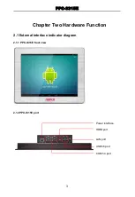
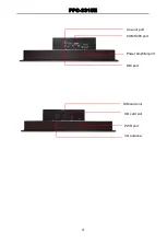
Page 11: ...Chapter Two Hardware Function...

Page 12: ...PPC 3315E 3 Chapter Two Hardware Function 2 1 External interface indicator diagram 2 1 1 PPC 3315E front view 2 1 2PPC 3315E port LAN port USB1 6 port COM1 4 port HDMI port Power interface...

Page 13: ...PPC 3315E 4 Line out port MIC port COM5 485 port Power amplifier port SD card slot SIM card slot 3G antenna PWR port...

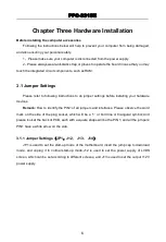
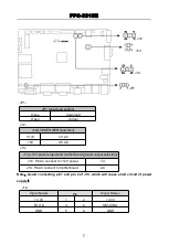
Page 14: ...Chapter Three Hardware Installa tion...

Page 15: ...to do jumper settings before installing your hardware devices Remark How to identify the PIN1 of all jumpers and interfaces Please observe the word mark on the side of the plug socket which will be a...

Page 16: ...12V power output and motherboard ground output selection J14 Pin A4 connect to 12V power 1 3 J14 Pin A3 connect to motherboard ground 2 4 Note Avoid connecting pin1 and pin 2 of J13 which will cause...

Page 17: ...printing on the complete machine COM3 COM4 in which COM1_3 port has RTS CTS function COM4_5 do not has RTS CTS function The mapping relationship of serial port RS232 is as follows Corresponding relati...

Page 18: ...serial port 485 is as follows Corresponding relationship of serial port 485 485 serial port dev ttymxc1 3 2 2 SATA Port SATA Provide 1x 7Pin SATA signal port and 4Pin SATA power interface SATA signal...

Page 19: ...USB4 6 J6 J7 J8 Provide 8x USB 2 0 port 5x standard USB2 0 port USB4 can choose J8 USB5 can be used as WIFI 1x OTG function USB2 0 standard port can choose J6 1x USB2 0 socket J7 MINI PCIE slot has 1x...

Page 20: ...CC 2 USB DATA 3 USB DATA 4 GND 5 GND J8 optional Pin Signal Names 1 VCC 2 USB DATA 3 USB DATA 4 GND 5 GND 3 2 4 Ethernet Port LAN Provide 1xPHY port chip model AR8033 Yellow for data transmission Gree...

Page 21: ...MB 7500 adopt SGTL5000 XNAA3 audio control chip and TI power amplifier chip Green for audio output port Line out Pink for microphone input port MIC in J18 for audio pin Amplifier out interface is Euro...

Page 22: ..._TX1_P 9 10 GND LVDS0_TX2_N 11 12 L0_TX2_P GND 13 14 L0_CLK_N LVDS_CLK_P 15 16 GND LVDS0_TX3_N 17 18 L0_TX3_P RI_UD 19 20 SELLVDS LVDS2 Signal Names Pin Signal Names VDD 1 2 VDD VDD 3 4 NC GND 5 6 GND...

Page 23: ...DS1_CLK_P LVDS1_TX3_N 29 30 LVDS1_TX3_P J11 Backlight power supply and control Pin Signal Names 1 12V 2 12V 3 Backlight on off 4 Backlight PWM 5 GND 6 GND VGA Signal Names Pin Signal Names VGAR 1 2 GN...

Page 24: ...8 Power Supply and System Indicator LED When the system is powered on the power indicator light is green when the motherboard is powered on normally when the system is powered off the power indicator...

Page 25: ...PPC 3315E 16 3 2 9 Four wire touch screen interface J4 Motherboard provide 1x four wire resistance touch J4 optional J4 Pin Signal Names 1 Y 2 X LED J4...

Page 26: ..._COL2 EIM_D16 5 6 GPIO17 EIM_D18 7 8 GPIO18 EIM_D17 9 10 SD2_CMD 3 2 11 Front Panel Interface JFP RSTSW JFP_RST is reboot function the restart of low pulse needs software cooperation it can also be re...

Page 27: ...PPC 3315E 18 JFP Signal Names Pin Pin Signal Names JFP_RST 1 2 GND JFP_PWRSW 3 4 GND 3 2 12 Fan Interface SYS_FAN JFP RSTSW SYS_FAN...

Page 28: ...13 MINI PCIe Port Motherboard provide 1x MINI PCIe slot users can expand Mini PCIe devices according to their own needs If you use mini PCIe wireless network card you can display the status of wirele...

Page 29: ...Chapter Four Software Function...

Page 30: ...LCD screen 4 1 2 USB 6x USB port support USB flash disk USB keyboard mouse and other devices USB flash disk auto mount directory mnt udisk or udisk 4 1 3 COM Serial port operation node dev ttymxc0 de...

Page 31: ...s 4 1 10 Sound Card Support local sound card and HDMI dual channel sound card Local sound card supports a pair of independent headphone and MIC 4 1 11 Camera Support USB camera and CVBS port camera 4...

Page 32: ...Appen dix...

Page 33: ...ions Here it refers to a system level chipset structured by South bridge North bridge Chipset decides the structure and main functions of motherboard CMOS Complementary Metal Oxide Semiconductor which...

Page 34: ...is often used to indicate information directly for example to indicate power on or HDD working normally PnP It is a specification that allows PC to configure its external devices automatically and it...

Page 35: ......

Reviews: