5 Parameters
BU 0500 EN-1516
135
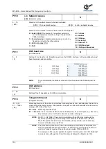
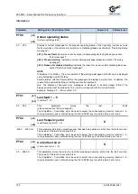
P506
Automatic error
acknowledgement
(Automatic error acknowledgement)
S
0 ... 7
{ 0 }
In addition to the manual error acknowledgement, an automatic one can also be selected.
0 =
No automatic
error acknowledgement.
1 ... 5 =
Number
of permissible automatic error acknowledgements within one mains-on cycle.
After mains off and switch on again, the full amount is again available.
6 =
Always:
an error message will always be acknowledged automatically if the cause of
the error is no longer present.
7 =
Via Deactivate enable:
acknowledgement is only possible using the OK / ENTER key
or by mains switch-off. No acknowledgement is implemented by removing the enable!
NOTE:
If (P428) is parameterised to "ON", parameter (P506) "Automatic error acknowledgement"
must not be parameterised to setting 6 "Always" as otherwise the device or system is endangered
due to the possibility of continuous restarting in the case of an active error (e.g. short-circuit to
earth / short circuit).
Pos: 311 /Anleitungen/Elektronik/FU und Starter/5. Parameter/Parameterauflistung (P000 ...)/P500-P599/Parameter P507 – PPO-Typ @ 0\mod_1328091974415_388.docx @ 11042 @ @ 1
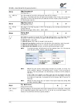
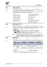
P507
PPO-Type
(PPO-
Type)
1 ... 4
{ 1 }
This parameter can only be used with the technology unit Profibus, DeviceNet or InterBus.
See also the relevant section of the corresponding supplementary BUS manual.
Pos: 312 /Anleitungen/Elektronik/FU und Starter/5. Parameter/Parameterauflistung (P000 ...)/P500-P599/Parameter P508 – Profibus-Adresse @ 0\mod_1328092017167_388.docx @ 11065 @ @ 1
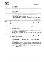
P508
Profibus address
(Profibus address)
1 ... 126
{ 1 }
Profibus address, only with the technology unit Profibus
See also the additional description for the Profibus control BU 0020
Pos: 313 /Anleitungen/Elektronik/FU und Starter/5. Parameter/Parameterauflistung (P000 ...)/P500-P599/Parameter P509 – Quelle Steuerwort @ 0\mod_1328092104264_388.docx @ 11088 @ @ 1
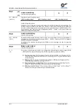
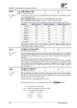
P509
Source Control Word
(Source control word)
0 ... 10
{ 0 }
Selection of the interface via which the FI is controlled.
0 = Control terminals or keyboard control
** with the ControlBox (if P510=0), the
ParameterBox (not ext. p-box) or via BUS I/O Bits.
1 = Only control terminals
, the FI can only be controlled via the digital and analog inputs or via
the bus I/O Bits.
2 = USS
control word *, the control signals (enable, direction of rotation, ...) are transferred via the
RS485 interface. The setpoint is transferred via the analog input or the fixed frequencies.
This setting should also be selected if communication via Modbus RTU is intended. The
frequency inverter automatically detects whether this is a USS protocol or a Modbus
protocol.
3 = CAN
control word *
4 = Profibus
control word *
5 = InterBus
control word *
6 = CANopen
control word *
7 = DeviceNet
control word *
8 = Ethernet TU***
control word*
9 = CAN Broadcast
*
10 = CANopen Broadcast *
*) Keyboard control (ControlBox, ParameterBox, PotentiometerBox) is blocked,
parameterisation is still possible.
**) If the communication during keyboard control is interrupted (time out 0.5 sec),
the FI will block without an error message.
***) The
Ethernet TU
setting must be used for all NORD Ethernet-based bus systems (e.g.:
EtherCAT: SK TU3-ECT, PROFINET: SK TU3-PNT).
Note:
Parameterisation of a frequency inverter via a field bus connection requires
parameter (P509) "Control Terminals" to be set to the appropriate bus system
Pos: 314 /Anleitungen/Elektronik/FU und Starter/5. Parameter/Parameterauflistung (P000 ...)/P500-P599/Parameter P510 – Quelle Sollwerte @ 0\mod_1328092251176_388.docx @ 11111 @ @ 1
NOTE:
For details about the respective Bus systems please
refer to the respective Options descriptions.
Summary of Contents for BU 0500
Page 1: ...EN BU 0500 SK 500E Users Manual for Frequency Inverters ...
Page 211: ......
Page 212: ...6075002 3021 ...


