3 Optional equiment
BU 0750 GB
Technical design subject to change
35
3.2.5 Profibus module
(SK TU2-PBR, part no.: 275130070)
(SK TU2-PBR-C, part no.: 275170070)
(SK TU2-PBR-24V, part no.: 275130110)
(SK TU2-PBR-24V-C, part no.: 275170110)
(SK TU2-PBR-KL, part no.: 275130065)
(SK TU2-PBR-KL-C, part no.: 275170065)
W
ith the Profibus system, data can be exchanged among a major number of automation devices whatever
their description. Stored-program controllers, PC's, operation and monitoring units, all of these are enabled to
communicate in serial bit mode via a single bus.
PROFIBUS DP is used mainly for sensor and actor communication where very short system response is re-
quired. PROFIBUS DP is a most interesting alternative to parallel signal transmission at 24 volts which is rather
costly, and is immensely suitable for the transmission of measured values. Optimized with regard to the speed
of transmission it ensures, this PROFIBUS version is used e.g. to operate frequency inverters which are con-
trolled by automation devices.
The data exchange is defined in the DIN 19245 standards Parts 1 and 2 as well as in a number of supple-
ments contained in Part 3 of this standard and dealing with specific uses. The PROFIBUS is being included
into the European field bus standard pr EN 50170 as Eurpean field bus standardization proceeeds. The termi-
nating resistor for the last unit connected to the bus is contained in the PROFIBUS standard connector.
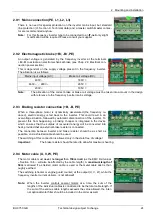
Profibus status LEDs
BR (green)
BUS ready
BE (red)
BUS error
NOTE:
For more detailed information please
refer to the
BU 0020
Operating Instructions or contact the
supplier of the frequency inverter.
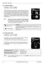
3.2.6 CANopen bus module
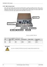
SK TU2-CAO, part no.: 275130100) (SK TU2-CAO-C, part no.: 275170100)
The CANopen interface on the NORDAC frequency inverters enables parame-
terisation and control of the devices in accordance with the standardized
CANopen specification. CANopen provides for addressing up to 127 units con-
nected to a single bus. A terminating resistor is integrated in the module and
can be activated when required. Transmission speed (10Kbaud and
500Kbaud) and the bus address can be set with rotary coding switches or in
the applicable parameters.
NOTE:
For more detailed information please refer to the
BU 0060
Operating Instructions or contact the
supplier of the frequency inverter.
CANopen status LEDs
CR (green)
CANopen RUN LED
CE (red)
CANopen ERROR LED
Module status LEDs
DR (green)
Module status
DE (red)
Module error

