3.3 Overview of the customer interfaces
BU 0750 GB
Technical design subject to change
39
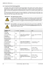
NOTE
regarding the 5V / 15V power supply units
Some of the customer interfaces and special extension modules have got more voltage sources
than one (5V / 15V) which can be used by external devices. The maximum allowable external load
current is 300mA. While this current amount can be collected from one or more power supply
points, the sum current must not exceed 300mA.
All control voltages are related to a common ground potential!
The potentials AGND /0V and GND /0V are interconnected by circuits inside the device.
3.3.1 How to assemble the custom interfaces
1. Switch off the mains voltage, wait a few
minutes as specified above.
2. Loosen the 8 screws with which the in-
verter cover is attached, and take care
not to pull of the PE conductor.
3. Insert the customer unit into the left guide
rail by pushing it lightly until it clicks into
place.
4. After unlatching the connector pull it off
and establish the necessary connections.
Afterwards push the connection pins on
until they lock.
5. Reattach all covers.
WARNING
Any installation work must be performed by properly qualified personnel exclusively who can be relied
upon to observe all of the safety and warning information provided in this manual.
Never plug in or remove a customer interface when the inverter is still connected to supply.
Whenever a module has been inserted, exchanged or removed, the FI will acknowledge this opera-
tion by putting out the E017 message
Change of customer interface
.
All PE connections must be reestablished!
IMPORTANT
The PE connection must absolutely be
reestablished. Otherwise operation of
the device is not permitted (see fig. op-
posite)!


