BU 0750 GB
Technical design subject to change
95
Parameter
Setting value / Description / Note
Parameter
set
Available with option
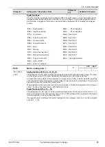
3 =
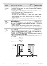
- 10V to +10V:
When a setpoint less than the 0% aligned value (P402) is applied, a reversal of
the phase sequence will result. This effect can be used to conveniently ensure a reversal of the
phase sequence by means of a simple voltage source and a potentiometer.
Setting example for an internal setpoint including a phase sequence reversal: P402 = 5V,
P104 = 0Hz, potentiometer 0–10V the phase sequence will be reversed at 5V with the
potentiometer at midway position.
The drive will stop the moment phase sequence reversal takes place (hysteresis = P505),
provided that the minimum frequency (P104) is less than the absolute minimum frequency
(P505). A brake controlled by the frequency inverter did not take hold in the hysteresis
range.
When the minimum frequency (P104) is greater than the absolute minimum frequency
(P505), the drive will be subject to phase sequence reversal when the value defined as
minimum frequency is reached. The FI will supply the minimum frequency (P104) in the
hysteresis range P104, a brake controlled by the FI does not take hold.
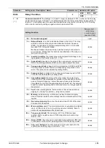
P402
Adjust 1: 0%
BSC
STD
MLT
-50.0...50.0 V
[ 0.0 ]
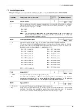
This parameter is used to set the voltage which is intended to correspond with the minimum value of
the function assigned to analogue input 1. The factory setting (setpoint) provides for this value to be
equal to the setpoint set in the P104 >Minimum frequency< parameter.
Typical setpoints and settings required to ensure them:
0 – 10V
0.0 V
2 – 10 V
2.0 V (with function 0-10V monitored)
0 – 20 mA
0.0 V (internal resistance approx. 250 )
4 – 20 mA
1.0 V (internal resistance approx. 250 )
P403
Adjust 1: 100%
BSC
STD
MLT
-50.0...50.0 V
[ 10.0 ]
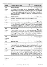
This parameter is used to set the voltage which is intended to correspond with the maximum value
of the function assigned to analogue input 1.
The factory setting (setpoint) provides for this value to be equal to the setpoint set in the P105
>Maximum frequency< parameter.
Typical setpoints and settings required to ensure them:
0 – 10 V
10.0 V
2 – 10 V
10.0 V (with function 0-10V monitored)
0 – 20 mA
5.0 V (internal resistance approx. 250 )
4 – 20 mA
5.0 V (internal resistance approx. 250 )
P400 ... P403
P401 = 0
0
–
10V limited
Ausgangs-
frequenz
Sollwert-
spannung
P104
P105
P403
P402
0,0V
2,5V
5,0V
z.B.
10,0V
positiv
P401 = 1
0
–
10V not limited
Ausgangs-
frequenz
Sollwert-
spannung
P104
P105
0,0V
2,5V
5,0V
z.B.
10,0V
positiv
negativ
P403
P402


