NORDAC SK 5xxE Manual
90
Subject to technical alterations
BU 0500 GB
Parameter
Set value / Description / Note
Device
Supervisor
Parameter
set
P415
PID control D-component
S P
0 ... 400.0 %ms
[ 1.0 ]
This parameter is only effective when the
function PID actual frequency
is selected.
If there is a rule deviation, the D-component of the PID controller determines the frequency
change multiplied by time (%ms).
If one of the analog inputs is set in the
function actual value process controller
, this parameter
determines the controller limitation (%) after the PI controller. For further details, see Section 8.2.
P416
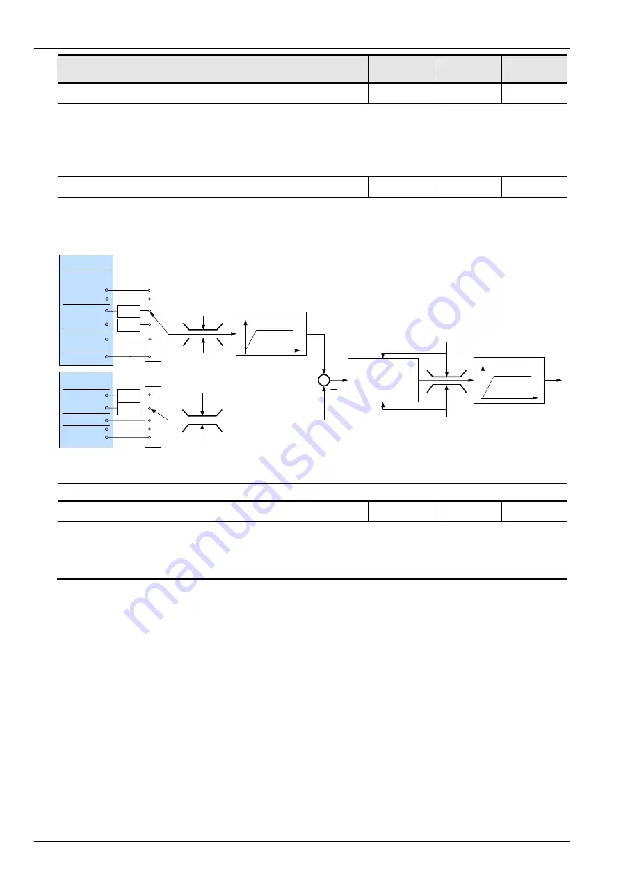
Ramp time PI setpoint.
S P
0.00 ... 99.99s
[ 2.00 ]
This parameter is only effective when the function PID actual frequency is selected.
Ramp for PI setpoint
PID controller
P413 (P-component)
P414 ( I-component)
P415 (D-component)
Frequency ramp
P102, P103
Ramp setpoint
P416
Maximum frequency P105
(monitored, limited)
Maximum frequency P105
(unlimited)
Minimum frequency P104
(monitored, limited)
- Maximum frequency P105
(unlimited)
Maximum
frequency P105
Minimum
frequency P104
Maximum frequency
auxiliary setpoint P410
Minimum frequency
auxiliary setpoint P411
Analog input 1
Analog input 2
Bus setpoint 3
Bus setpoint 2
Auxiliary
setpoint sources
PotentiometerBox
P400-P404
Scaling
P405-P409
Scaling
Analog input 1
Analog input 2
Bus setpoint 1,2,3
Main
setpoint sources
Fixed frequency 1-5
Controlbox /
PotentiometerBox
Jog frequency
P400-P404
Scaling
P405-P409
Scaling
Also in
combination, se e
se tpoint adjustme nt
Fig.: Flow diagram for PID controller
P417
Offset analog output 1
S P
-10.0 ... 10.0 V
[ 0.0 ]
In the analog output function an offset can be entered to simplify the processing of the analog
signal in other equipment.
If the analog output has been programmed with a digital function, then the difference between the
switch-on point and the switch-off point can be set in this parameter (hysteresis).


