background image

PRE-OPERATION


BC 60 "Trailblazer" Brushcutter


Section 2-4 


DEC/2012 (49458202/8203) 

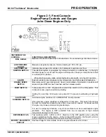
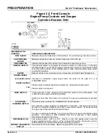
Figure 3-2. Front Console 

Engine/Pump Controls and Gauges 

Cummins Engines Only 


INSTRUMENT OR  
CONTROL 

 
FUNCTIONAL DESCRIPTION

FUEL GAUGE 

Measures the level of diesel fuel in the fuel tank.  Do not allow to go into the red zone.
 

AIR PRESSURE 

GAUGE 

Measures air system pressure.  Normal reading is 105 to 120 psi. 

SPEEDOMETER 

Indicates travel speed of machine in both kilometers and miles per hour.

IGNITION SWITCH 

The electrical system is energized by turning the switch (or optional key) to the right.  
Electrical power is cut off  and the engine will stop when the key is turned to the full left 
or vertical (OFF) position. When starting engine, make certain hydraulic pump switch  
is in the OFF position

ALARM 

Buzzer sounds on low air pressure, low oil pressure, and high coolant temperature. 

ENGINE SPEED  


Increase/Decrease 


High/Bump Mode 


Low 


Increases or decreases engine speed when the switch to the right of it is in 
HIGH/BUMP Mode. 
 
Places engine to highest speed and enables the  Increase/Decrease switch. 
 
Places engine in low speed. 
 

PUMP SWITCH 

Turns pump ON or OFF.  Engine will not start if the switch is in the ON position.  This 
is done to reduce engine load during starting. 
 
If idling for more than 30 minutes, turn pump OFF to prevent overheating of hydraulic 
oil. 

SHUTDOWN 

OVERRIDE SWITCH 

Overrides engine shutdown for  EMERGENCY travel purposes.   
 
Once pressed, engine shutdown is delayed for 30 seconds.  This switch should only 
be used in emergency situations where track movement is needed.  Continual override 
of engine may cause permanent engine damage. 
 
For use in emergency situations  only, when machine must be moved despite engine 
problems.  The engine is NOT protected from low oil pressure or high coolant 
temperature damage in this mode.

REVERSIBLE FAN 

Two position switch.  AUTO or OFF.  Must be in the OFF position when using the 
snap-on winterfront on the engine.    When in the AUTO position, the fan will cycle in a 
certain direction for a timed amount before switching to reverse. 

MURPHY DIAGNOSTIC 

DISPLAY 

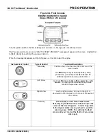
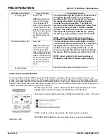
See Figure 3A for more details.  Refer to engine tab for error codes. 

SHUTDOWN 
OVERRIDE

Summary of Contents for Trailblazer BC60

Page 1: ...0 and Above Reorder Part 49458202 Last Revision Rev OCT 2012 Read and fully understand the precautions contained in this manual before operating or servicing this machine Refer to Section 1 for import...

Page 2: ......

Page 3: ...anent part of your machine and should remain with the machine at all times Additional copies of this manual are available either as a part Operation Manual only or a whole operation and parts manual a...

Page 4: ...we have OSHA Form 20 Safety Data Sheets available that cover the material contained in this machine If you are interested in receiving this information please refer to the Name model and Serial Number...

Page 5: ...aw Blade Type 2 2 Engine 2 2 Hydraulic and Electrical System 2 2 Controls 2 3 Engine Pump Controls and Gauges 2 3 Engine Diagnostic Gauge Refer to Engine Manual for Diagnostic Codes 2 4 Travel Control...

Page 6: ...ance Chart 3 3 Detailed Instructions 3 5 Cutterhead Check 3 5 Brake Adjustments 3 5 Transmission level 3 6 Pump Drice 3 7 Rope Inspection 3 8 Sheave Inspection 3 9 Turbo 2000 Air 3 10 Oil Cooler 3 11...

Page 7: ...et anyone operate this machine without instruction Failure to understand the contents of this manual could result in serious personal injury or death SAFETY ALERT SYMBOLS These are the safety alert sy...

Page 8: ...certain the area around and under the machine is clear of obstructions and personnel Use care when climbing onto the machine Always use the steps and handrails provided If an area does not have tread...

Page 9: ...This machine was designed to be operated by two people 5 The machine is to be operated from the Operator s seats only Do NOT stand and operate this machine 6 Press the EMERGENCY STOP pushbutton on the...

Page 10: ...scalding when working with engine oils 6 Use only Nordco supplied repair parts for this machine Use of non OEM designed parts could comprise the integrity of this machine 7 There are welding cautions...

Page 11: ...njury or death Always extend BOTH cuttings arms while in superelevated areas Failure to do so may cause the machine to derail which will cause severe bodily injury or death Do not operate machine with...

Page 12: ...l systems or workheads in the full up and locked positions 4 When mechanical locking up of equipment is not feasible for maintenance lower the component to the ground prior to working on the equipment...

Page 13: ...eshooting for the hydraulic system and all piping and functional drawings for a standard machine and optional equipment Electrical includes electrical schematics distribution and control boxes and cab...

Page 14: ...ntinuous BHP 275 HP 2200 RPM Oil Capacity 32 5 Liters HYDRAULIC SYSTEM Pressure Settings Relief Valve Track Drive 5000 psi 345 bar Main Pump 22 GPM Mfr Relief Cartridge Valve Banks 2700 psi bar PNEUMA...

Page 15: ...r s Station This includes but is not limited to the front machine control console engine controls the propulsion controls and brake pedals Under no circumstances are there to be more riders on this ma...

Page 16: ...ion before shutting down the machine and attempting to troubleshoot the engine problems USE THIS SWITCH ONLY IN THE EVENT OF AN EMERGENCY ELECTRICAL SYSTEM The hydraulic functions of the machine are c...

Page 17: ...ch in position until desired engine RPM has been reached and then release switch PUMP SWITCH Turns pump ON or OFF Engine will not start if the switch is in the ON position This is done to reduce engin...

Page 18: ...is in HIGH BUMP Mode Places engine to highest speed and enables the Increase Decrease switch Places engine in low speed PUMP SWITCH Turns pump ON or OFF Engine will not start if the switch is in the O...

Page 19: ...is touched to either enter or exit the menu screens The Menu key is only used during factory setup procedures See Component Data Section for additional operation and setup instructions Left Arrow Use...

Page 20: ...orrect the fault The Red Shutdown Derate LED signals a fault has occurred that requires immediate action Shutdown the engine but do not turn the switch to the off position You must go through the code...

Page 21: ...before using the brake pedal or else the track drive system could become damaged SUSPENSION LOCKOUT SWITCH UP DOWN A stiffer ride can be achieved using the suspension lock out switch This may be prefe...

Page 22: ...h Gear LED indicates the current GEAR Should be in 1st gear when starting up Propulsion EDC MUST be in neutral when changing gears Gear switches have no power if EDC is in FWD or REV Used for working...

Page 23: ...t accidental startup of cutterheads After energizing the cutterheads reduce the engine speed to idle speed and make certain that the area around the machine is safe to engage the cutterheads The cutte...

Page 24: ...e speed and make certain that the area around the machine is safe to engage the cutterheads The cutter enabled light above the switch will light up to indicate that the Cutterheads have been energized...

Page 25: ...ght will illuminate when switch is in the ON position and will remain lit until switch or machine has been turned off TRAVEL DIRECTION FWD REV Used to select the direction of travel Selects the front...

Page 26: ...ing PARKING BRAKE Diamond shaped button below the ignition key Press to apply brakes pull to release brakes EMERGENCY PUMP Momentary switch hold to use pump Use pump in 20 second increments only CAB H...

Page 27: ...visual check OFF SWITCH 2 Turns the heater off VENTILATOR FAN 3 Use this button to start the heater in ventilation mode In this mode the heat selector control knob is not active If the heater is in th...

Page 28: ...brake de ice Pull button to deactivate Use knob to adjust the pressure applied to the brake shoe This is done to keep ice from forming on the shoes Pressure gauge shows the pressure Pressure System Di...

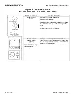
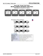
Page 29: ...BC 60 Trailblazer Brushcutter PRE OPERATION DEC 2012 49458202 8203 Section 2 15 Figure 8A Center Post Panel MISCELLANEOUS OPTIONAL CONTROLS PRESSURE SYSTEM DISPLAY GAUGE...

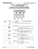
Page 30: ...ement stops at last position Tilts Back cutterhead up front cutterhead down 3 Cutter Head Rotate Push Release Pull Rotates front cutter head out from machine Movement stops at last position Rotates fr...

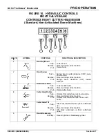
Page 31: ...CCW away from machine Movement stops at last position Swings boom clockwise CW toward machine 3 Outer Boom Pivot Push Release Pull Lowers cutter head Movement stops at last position Raises cutter head...

Page 32: ...ext to the battery box Two position switch marked with ON OFF plaque This must be OFF and cover locked during service 4 Hydraulic Oil Tank Sight Level and Optional OilTemperature Gauge Located on hydr...

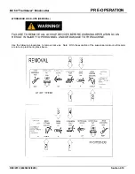
Page 33: ...OCK UPS REMOVAL FAILURE TO REMOVE ALL LOCKUP DEVICES BEFORE WORKING OPERATIONS CAN RESULT IN INJURY TO PERSONNEL AND OR DAMAGE TO THE MACHINE Use the following procedures to remove lock ups Note With...

Page 34: ...cure cutterheads using chain and hook Remove chain and hook for work mode Remove lockup hook from cutterhead Note This may require rotating cutterhead in or out to maneuver the hook out of the eyelet...

Page 35: ...INSTALLATION FAILURE TO ENGAGE ALL LOCKUP DEVICES BEFORE PROPELLING AT TRAVEL SPEED CAN RESULT IN INJURY TO PERSONNEL AND OR DAMAGE TO THE MACHINE Use the following procedures to install lock ups Not...

Page 36: ...k for work mode Position the cutterhead so that it is in line with the boom use cutterhead rotate as required With the boom high enough to clear the boom cradle Swing the boom slowly toward the machin...

Page 37: ...up chains Raise turntable to maximum height Engage attachment lock using control in cab Lower turntable onto hooks Insert pin to prevent rotation Note Turntable locks MUST be removed prior to lowering...

Page 38: ...oil level and hydraulic oil level before attempting to start engine 2 Ensure that pump suction line gate valves are fully open 3 Make certain that the implement pump switch is in the OFF position 4 En...

Page 39: ...ONTROLS FUNCTION Air Brakes LOCK UP DEVICES ENGAGED Cutter Head Suspension Turntable MACHINE FLUID LEVEL CHECK See recommended fluids in Maintenance Section Hydraulic Oil Tank is full Fuel Tank is ful...

Page 40: ...TRAVEL OPERATION Before propelling this machine make certain that all lockups are in their proper position Check that suspension is not locked out for machines with optional suspension lockouts NOTE...

Page 41: ...wer using only the brake pedal When the Quick Stop Mode is activated application of either brake pedal automatically neutralizes the pump swash plate enabling the operator to stop the machine more qui...

Page 42: ...rhead assemblies Configuration 1 as shown in the drawing to the right will keep more of the debris around the track area when cutting To use this rotation configuration you need longer hoses to switch...

Page 43: ...DO NOT SIDE LOAD BOOMS Reduce travel speed or stop before cutting dense brush and trees Ease into objects allowing cutterheads to do the work 2 Do not attempt to cut trees more than 4 inches in diamet...

Page 44: ...S and DANGERS before starting the cutterhead motors 8 Pull the Motor Start control buttons for the Cutterhead motors Two on each side of upper control console 9 If working at speeds less than 12 mph e...

Page 45: ...3 Move the Turntable Valve hand lever upward and hold until the machine is fully raised off the track Release the lever 4 Use manpower to rotate the machine The wheels should be directly above the tr...

Page 46: ...at all lubricating oils fluids and filters are clean and maintained as outlined in this section It is important that lubrication is performed at the time intervals stated or else machine damage could...

Page 47: ...o 100 F 23 C to 37 8 C 80W 90 Above 100 F Above 37 8 C 85W 140 BLOOM MFG BOOM WINCH Break In Period 100 Hours Oil Change Schedule First 100 hours every 6 months thereafter Lubricant Type Bloom Ulltra...

Page 48: ...BC 60 Trailblazer Brushcutter MAINTENANCE AUGUST 2012 49458202 8203 Section 3 3...

Page 49: ...MAINTENANCE BC 60 Trailblazer Brushcutter Section 3 4 AUGUST 2012 49458202 8203...

Page 50: ...ly torqued and or the cartridge bearings are worn 4 Insure that cotter KEY in cutter shaft is properly installed 5 Grease cutterhead until grease can be seen exiting between cutterhead frame and flywh...

Page 51: ...er and under normal operating conditions it is recommended that the oil be changed after every six months of operation The oil in the unit should be changed whenever the oil level shows traces of dirt...

Page 52: ...oil fill before checking or adding oil 3 It is recommended that lubricating oil be changed after the first 500 hours of service 4 Thereafter and under normal operating conditions it is recommended tha...

Page 53: ...e tow areas must be inspected The fitting that is attached to the rope and the condition of the rope where it enters the attachment The general condition of the drum should be inspected carefully If t...

Page 54: ...ng or damage from two blocking Undue looseness in the bearing or bushing should be noted The sheave s groove surface should be smooth and slightly larger than the wire rope being used Proper maintenan...

Page 55: ...ied apply a light coating on o ring Install o ring on adapter stud 6 Apply a generous coat of grease on the new desiccant cartridge gasket surface 7 Thread new cartridge onto adaptor stud turning cloc...

Page 56: ...ion 3 11 T9 Clean the Oil Cooler Brush debris from outside of oil cooler with a soft brush Inspect fins for damage or obstructions every 200 hours of operation Blow out debris from cooler fins with lo...

Page 57: ...il has not been added to the crankcase contact the engine maker s authorized service outlet listed in the Engine Manual Fuel or coolant dilution of lube oil can result in serious engine damage Never o...

Page 58: ...rs Care should be taken to keep the hydraulic oil free of dust water sealing compounds and other foreign matter While using the sight gauge verify oil quality If oil becomes dark or milky colored it s...

Page 59: ...out plug attached to cable 3 Using Allen wrench turn screw 2 inside of plug housing clockwise to open counterclockwise to close 4 Remove six capscrews and lift off front cover Reverse process to reatt...

Page 60: ...rs operator control box footswitches and logic box are required Harnesses that may not have proper connection could cause problems in starting and stopping the machine In addition to harness connectio...

Page 61: ...r contamination occurs because even small amounts of water can affect system performance as well as induce corrosion and oil breakdown T20 Check Air Cleaner Indicators Engine and Cab Do not allow air...

Page 62: ...in that the Battery Disconnect Switch is in the OFF position Inspect the terminals and cable clamps regularly Clean battery terminals and cable clamps when corrosion is visible Have excessively corrod...

Page 63: ...lblazer Brushcutter Section 3 18 AUGUST 2012 49458202 8203 T23 Run Pressure Checks on Main Pump and Propulsion Blow out the vents on a monthly basis Clean the screen filter on a weekly basis more ofte...

Page 64: ...BC 60 Trailblazer Brushcutter MAINTENANCE MARCH 2011 49458201 Section 3 21 TORQUE REQUIREMENTS...

Page 65: ...ine hydraulics electrical and mechanical pneumatic and is intended to give you basic troubleshooting guidelines Local conditions and operating methods may result in problems causes and remedies not co...

Page 66: ...voltage regulator alternator and or electrical system The following precautions should be taken to minimize the possibilities of injuries from heated diesel fuel 1 Whenever possible it is recommended...

Page 67: ...or cracked battery case 5 Inspect for overheated parts after the unit has been stopped for a while They will often smell like burned insulation Put your hand on the alternator Heat in these parts when...

Page 68: ...tripped Reset circuit breaker Horn defective Check horn repair or replace Horn relay defective Check relay Horn switch defective Check switch repair or replace Backup Alarm does not sound Connection...

Page 69: ...nection on relay Tighten connection Brake lights do not work Wiring harness defective Check harness repair or replace Connection at light loose Tighten connection Circuit breaker tripped Reset circuit...

Page 70: ...anical system for clues to the malfunction Check to see if the unit can be operated without further damage Always turn off machine when performing maintenance making adjustments or whenever unintended...

Page 71: ...spool Inspect and repair Winch motor defective Inspect repair or replace Boom will not swing Flow control valves improperly adjusted Inspect and adjust as necessary Piston bypassing Repair cylinder St...

Page 72: ...place Excessive Vibration During High Speed Travel Journal bearings are dry Replace Suspension wear plates are worn Replace Universal joints worn Replace Uneven wheel diameters Resurface or replace Lo...

Reviews: