background image

Page 2 of 6

www.fast-stat.com

Troubleshooting

No Power at Thermostat

A

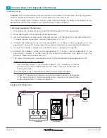
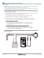
1.  Remove the thermostat from its subbase. Set the multimeter to ‘Volts AC’ (V~) and measure 

between the subbase ‘R’ (or ‘Rc’) and ‘C’ terminals. It should read between 23-28 volts.


If the thermostat has both ‘Rh’ and ‘Rc’ terminals

  If the system has a single transformer

If the multimeter reads 0 volts

Problem:

 The Common Maker and thermostat are installed but the thermostat is not receiving 

power.

If the multimeter reads below 23 volts

  If the system has two transformers (one for heating, one for cooling)

• 

Thermostats typically require power on ‘Rc’ to function. The ‘Rc’ and ‘Rh’ 
terminals should be jumpered together to provide power to both the 
thermostat and heating equipment.

• 

Smart thermostats may have an internal jumper that connects ‘Rh’ and 
‘Rc’. This is configured in the thermostat settings.

• 

The power to the equipment should have been turned off during 
installation. Ensure it was turned back on.

• 

Check each wire nut for broken wires. Ensure the wire nut is tightened 
enough stay on when lightly pulled.

• 

Some equipment may have a control panel cabinet with a ‘door safety 
switch’ that disconnects power while the cabinet door is open. Ensure 
the door is closed while testing.

• 

Check the fuse at the equipment to see if it was blown during installation. 
If it did, check the Common Maker wiring for errors and replace the fuse.

• 

If the problem still persists, proceed to the ‘Thermostat Cable Test’ (page 4).

• 

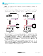
Some equipment may not have a transformer large enough to power 
a Wi-Fi thermostat. If the voltage drops below 23 volts when the 
thermostat is connected and the equipment is on, a second transformer 
will have to be installed. See diagram ‘C’ on the instructions.

• 

The Common Maker must be installed on the cooling equipment. See 
diagram ‘G’ in ‘Additional Wiring Diagrams’.

• 

If the thermostat has a jumper between ‘Rh’ and ‘Rc’, remove it.

• 

Smart thermostats may have an internal jumper that connects ‘Rh’ and 
‘Rc’. This is configured in the thermostat settings.

Summary of Contents for Common Maker

Page 1: ... Contains two or more wires Thermostat Subbase The component attached to the wall that the thermostat fits onto Contains the connections to the thermostat cable wires Open Circuit A break in a wire that prevents electricity from flowing through it Short Circuit An unintended connection between two or more wires in the thermostat cable or between a wire and electrical ground Common Terms Overview N...

Page 2: ...rned off during installation Ensure it was turned back on Check each wire nut for broken wires Ensure the wire nut is tightened enough stay on when lightly pulled Some equipment may have a control panel cabinet with a door safety switch that disconnects power while the cabinet door is open Ensure the door is closed while testing Check the fuse at the equipment to see if it was blown during install...

Page 3: ...damage to the equipment 3 Connect the Sender s white wire directly to the thermostat R or Rc terminal This should activate the equipment If the equipment activates from this test the thermostat is not functioning properly 4 Using a wire jumper between the two terminals the Receiver s red and white wires are connected to This should start the equipment If the equipment does not start from this test...

Page 4: ...eceiver should close causing the multimeter to read between 0 1Ω Problem The Common Maker and thermostat are installed the thermostat is receiving power and the Equipment Will Not Start section did not resolve the issue This test will determine if there is a fault in the Common Maker It can be tested either at the equipment transformer page 5 or a bench power supply page 6 Testing at Equipment Tra...

Page 5: ...C power supply 3 Connect the Receiver s purple wire to the Sender s purple wire 4 Connect the Sender s white wire to the other side of the 24V AC power supply 5 The relay in the Receiver should close causing the multimeter to read between 0 1Ω If the resistance is not less than 1Ω If the resistance is less than 1Ω but it doesn t work when installed The Common Maker is not working properly It is co...

Page 6: ... multimeter to Resistance Ω At the location of the equipment measure between the two wires in the thermostat cable If the thermostat cable has more than two wires measure the resistance between each combination of two wires The resistance should typically read between 0 5 to 5Ω for each test Problem The Common Maker and thermostat are installed the thermostat is not receiving power and the No Powe...

Reviews: