


Page 6 of 6
www.fast-stat.com
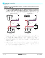
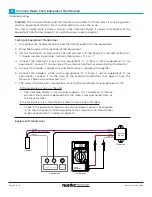
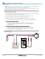
Troubleshooting
Thermostat Cable Test
C
2. Disconnect the thermostat cable wires from the thermostat and equipment. Separate the
wires so they are not making contact with anything. Set the multimeter to ‘Resistance’ (
Ω
).
At the location of the equipment, measure between the two wires in the thermostat cable.
If the thermostat cable has more than two wires, measure the resistance between each
combination of two wires. Then measure between each wire and electrical ground. The
resistance should read ‘open circuit’, normally displayed as ‘OL’ or ‘-1’ for each test.
1. Disconnect the thermostat cable wires from the thermostat and equipment. Separate the
wires so they are not making contact with anything. Set the multimeter to ‘AC Volts’ (V~)
and check for voltage between the two wires in the thermostat cable. If the thermostat
cable has more than two wires, check for voltage between each combination of two wires.
3. Disconnect the thermostat cable wires from the thermostat and equipment. At the
thermostat, tie the thermostat cable wires together. Set the multimeter to ‘Resistance’ (
Ω
).
At the location of the equipment, measure between the two wires in the thermostat cable.
If the thermostat cable has more than two wires, measure the resistance between each
combination of two wires. The resistance should typically read between 0.5 to 5
Ω
for each
test.
Problem:
The Common Maker and thermostat are installed, the thermostat is not receiving
power, and the ‘No Power at Thermostat’ section did not resolve the issue.
This test will determine if there is a fault in the thermostat cable.
Voltage Test
Open Circuit Test
Short Circuit Test
If a voltage is measured
If the resistance is not between 0.5 to 5
Ω
If the resistance is not ‘OL’ or ‘-1’
•
There is a device (relay, transformer, etc) connected between the
thermostat and equipment. Locate the device and contact our technical
support line to determine how the Common Maker should be installed.
•
There is a break in at least one of the wires that will prevent it from
working. If there are not at least two functional wires, a new cable will
have to be installed.
•
There is a short between at least two wires in the thermostat cable, or
between at least one wire and ground that will prevent it from working.
If there are not at least two functional wires, a new cable will have to be
installed.


