background image

30

PART LIST—Model No. NATL81205.0

R0805A

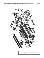
To locate the parts listed below, see the EXPLODED DRAWING attached in the centre of this manual.

1

2

Foot Rail Insert

2

1

Left Foot Rail

3

2

2” Belly Pan Screw

4

1

Front Left Endcap

5

2

Frame Pivot Bolt

6

2

Frame Pivot Spacer

7

1

Magnet

8

1

Front Roller/Pulley

9

5

Nut

10

1

Reed Switch/Sensor Wire

11

1

Upright Ground Wire

12

1

Reed Switch Clip

13

1

Lift Frame

14

1

Walking Belt

15 

14

Foot Rail Screw/Endcap Screw

16

1

Motor

17

1

Receptical

18

2

Motor Bolt

19

1

Front Roller Bushing

20

2

Frame Pivot Nut

21

1

Top Incline Bolt

22

1

Motor Belt

23

1

Hood

24

1

Incline Motor Bolt

25

2

Motor Bushing

26

1

Splitter

27

19

Electronics Screw

28

2

Foam Pad

29

1

Controller

30

1

Left Outside Housing

31

1

Motor Controller Wire

32

1

Front Roller Adj. Bolt

33

4

Pulse Bar Bolt

34

6

Roller Washer/Spring Washer

35

1

Left Roller Guard

36

1

Incline Motor

37

1

Incline Motor Stop

38

1

Motor Belly Pan

39

1

Audio Wire Nut

40

1

Static Decal

41

1

On/Off Switch

42

1

Power Cord

43

1

Right Roller Guard

44

4

Spring Bolt

45

4

Belt Guide Screw

46

2

Belt Guide

47

2

Isolator

48

1

Pulley Nut

49

1

Ground Screw

50

4

Spring Nut

51

1

Front Right Endcap

52

1

Walking Platform

53

2

Front Platform Screw

54

2

Rear Platform Screw

55

2

Spring Pad

56

2

Spring

57

1

Idler Ground Wire

58

1

Rear Endcap, Right

59

2

Rear Roller Adj. Bolt

60

1

Warning Decal

61

1

Allen Wrench

62

1

Rear Roller

63

1

Audio Wire

64

1

Chest Pulse Sensor

65

1

Pulse Bar

66

1

Pulse Wire

67

2

Spring Pad Screw

68

1

5/16 Allen Wrench

69

1

Uprights

70

1

Latch Knob Sleeve

71

1

Chest Strap

72

1

Roller Star Washer

73

1

Filter

74

1

Belly Pan Screw

75

1

Filter Wire

76

1

Bracket Bolt

77

8

Star Washer

78

2

Console Bolt

79

2

Upright Endcap

80

1

Access Door

81

1

Console Base

82

1

Console

83

2

Upright Cap

84

1

Key/Clip

85

1

iFIT.com Wire

86

1

Jack

87

1

Console Insert

88

1

Console Back

89

1

Releaseable Tie

90

14

Console Screw

91

2

Cable Tie Clamp

92

5

8” Cable Tie

93

2

Lift Pivot Bolt

94

2

Wheel Bolt

95

2

Wheel

96

1

Rear Endcap, Left

97

1

Grommet

98

1

Upright Wire Harness

99

6

Base Pad

100

12

3/4” Screw

Key No. Qty.

Description

Key No. Qty.

Description

Summary of Contents for 1500i Treadmill

Page 1: ...or damaged parts we will guarantee complete sat isfaction through direct assis tance from our factory TO AVOID DELAYS PLEASE CALL DIRECT TO OUR TOLL FREE CUSTOMER HOT LINE The trained technicians on...

Page 2: ...SE SENSOR 9 OPERATION AND ADJUSTMENT 10 HOW TO FOLD AND MOVE THE TREADMILL 24 TROUBLESHOOTING 26 CONDITIONING GUIDELINES 29 PART LIST 30 ORDERING REPLACEMENT PARTS Back Cover Note An EXPLODED DRAWING...

Page 3: ...3 conductor 1mm2 14 gauge cord that is no longer than 1 5 m 5 ft 12 Keep the power cord away from heated sur faces 13 Never move the walking belt while the power is turned off Do not operate the trea...

Page 4: ...the treadmill and before performing the main tenance and adjustment procedures de scribed in this manual Never remove the motor hood unless instructed to do so by an authorised service representative...

Page 5: ...ne number on the front cover of this man ual To help us assist you please note the product model number and serial number before calling The model number of the treadmill is NATL81205 0 The serial num...

Page 6: ...screwdriver wire cutters and rubber mallet For help identifying the assembly hardware see the hardware drawings below 6 w 123 2 1 2 Silver Screw 48 1 3 4 Tek Screw 58 4 Spacer Screw 60 2 1 Screw 148 4...

Page 7: ...nd the Wheel with two Wheel Bolts 94 and two Nuts 9 Do not overtighten the Wheel Bolts the Wheels should turn freely Attach the other Wheel 95 and Wheel Endcap 101 as described above With the help of...

Page 8: ...e a rubber mallet if necessary 106 69 77 77 78 Console Assembly 79 7 Press the Latch Knob Sleeve 70 into the left Upright 69 Note It may be helpful to use a rubber mallet to fully insert the Latch Kno...

Page 9: ...ic bag or other container that may trap moisture Do not expose the chest pulse sensor to direct sun light for extended periods of time do not expose it to temperatures above 50 C 120 F or below 10 C 1...

Page 10: ...g Important If the power cord is damaged it must be replaced with a manufacturer recommended power cord See drawing 1 Plug the indicated end of the power cord into the socket on the treadmill See draw...

Page 11: ...g a stereo audio cable you can connect the treadmill to your portable stereo home stereo computer or VCR and play special iFIT com MP3 CD and video programs iFIT com MP3 programs CDs and videocassette...

Page 12: ...g the Speed in crease and decrease buttons Each time a button is pressed the speed setting will change by 0 1 km h if a button is held down the speed setting will change in increments of 0 5 km h Note...

Page 13: ...ty all instructions in this section refer to kilometres The lower centre of the display will show the dis tance that you have walked or run during your workout To see the total number of kilometres th...

Page 14: ...lt increases and de creases To turn off the fan press the AutoBreeze Fan but ton again Note A few minutes after the walking belt is stopped the fan will automatically turn off When you are finished ex...

Page 15: ...the speed and or in cline of the treadmill is about to change the speed setting and or the incline setting will flash in the display to alert you When the first segment is completed all speed setting...

Page 16: ...the steps below to use a heart rate program Put on the chest pulse sensor You must wear the chest pulse sensor to use a heart rate program Insert the key into the console See HOW TO TURN ON THE POWER...

Page 17: ...s of tones will sound and the speed setting and the incline setting will flash in the display The program will continue in this way until the last segment ends The walking belt will then slow to a sto...

Page 18: ...If your stereo has a 3 5 mm LINE OUT jack see instruction B If your stereo has only a PHONES jack see instruction C A Plug one end of a long 3 5 mm to RCA stereo audio cable available at electronics...

Page 19: ...xt remove the wire that is currently plugged into the LINE OUT jack on your stereo and plug the wire into the unused side of the Y adaptor Plug the Y adaptor into the LINE OUT jack on your stereo Note...

Page 20: ...of this manual Follow the steps below to use an iFIT com MP3 CD or video program Insert the key into the console See HOW TO TURN ON THE POWER on page 12 Select the iFIT com mode To select the iFIT com...

Page 21: ...If the speed and or incline of the treadmill does not change when a chirp is heard Make sure that the letters iFIT appear in the display and that the time is not flashing in the display If the time is...

Page 22: ...down ends the program will begin and the walking belt will begin to move Hold the handrails step onto the walking belt and begin walking During the program an electronic chirping sound will alert you...

Page 23: ...he Speed increase button to change the unit of measurement IMPORTANT If a d appears in the upper centre of the display the console is in the demo mode This mode is intended to be used only when a trea...

Page 24: ...atch pin into the hole Make sure that the latch pin is fully in serted into the hole Note If the adjustment knob see page 23 hits the right upright press on the knob To protect the floor or carpet fro...

Page 25: ...hown Using your left hand pull the latch knob to the left and hold it Pivot the treadmill down until the frame is past the latch pin 2 Hold the treadmill firmly with both hands and lower the treadmill...

Page 26: ...s and then press the switch back in d Check the on off switch located on the treadmill near the power cord The switch must be in the on position PROBLEM The power turns off during use SOLUTION a Check...

Page 27: ...er cord in sert the key and run the treadmill for a few minutes Repeat until the walking belt is properly tightened c If the walking belt still slows when walked on see the front cover of this manual...

Page 28: ...the sensor unit and insert a new CR 2032 battery with the battery oriented so the writing on top Make sure that the rubber gasket is in place in the sensor unit Then reinsert the battery cover and tu...

Page 29: ...hat requires large amounts of oxygen for prolonged periods of time This increases the demand on the heart to pump blood to the muscles and on the lungs to oxygenate the blood For aerobic exercise adju...

Page 30: ...l 41 1 On Off Switch 42 1 Power Cord 43 1 Right Roller Guard 44 4 Spring Bolt 45 4 Belt Guide Screw 46 2 Belt Guide 47 2 Isolator 48 1 Pulley Nut 49 1 Ground Screw 50 4 Spring Nut 51 1 Front Right End...

Page 31: ...Gear Rack 130 4 Extension Leg Bolt 131 1 Circuit Breaker 132 1 Motor Isolator 133 1 Idler Arm 134 1 Idler Spring 135 2 Idler Arm Nylon Washer 136 1 Bracket Nut 137 1 Idler Pulley Washer 138 1 Idler Pu...

Page 32: ...30 55 56 50 44 34 67 44 50 34 56 67 119 90 118 55 45 129 45 129 45 46 47 47 28 140 43 34 59 35 15 15 100 22 16 132 18 25 18 133 134 137 48 138 9 54 105 135 28 141 15 15 15 15 15 15 100 146 146 144 14...

Page 33: ...83 83 100 95 9 101 142 99 26 64 71 126 112 49 114 99 148 103 102 99 148 103 102 77 78 65 106 98 66 66 106 77 11 77 33 77 33 27 90 115 81 90 107 90 90 107 116 82 84 87 108 90 88 40 90 90 90 90 90 90 80...

Page 34: ...to any economic loss loss of property loss of revenues or profits loss of enjoyment or use costs of removal or installation or other consequential damages of whatsoever nature Some states do not allo...

Reviews: