background image

33

NOTES

Summary of Contents for 23897.0

Page 1: ...NTACT THE STORE please contact Customer Care IMPORTANT Please register this product see the limited warranty on the back cover of this manual before contacting Customer Care CALL TOLL FREE 1 800 TO BE FIT 1 800 862 3348 Mon Fri 6 a m 6 p m MT Sat 8 a m 4 p m MT ON THE WEB www nordictrackservice com CAUTION Read all precautions and instruc tions in this manual before using this equipment Keep this ...

Page 2: ...cement decal Apply the decal in the loca tion shown Note The decal s may not be shown at actual size WARNING DECAL PLACEMENT 2 IMPORTANT PRECAUTIONS 3 BEFORE YOU BEGIN 4 PART IDENTIFICATION CHART 5 ASSEMBLY 6 HOW TO USE THE ELLIPTICAL 16 FCC INFORMATION 28 MAINTENANCE AND TROUBLESHOOTING 29 EXERCISE GUIDELINES 31 PART LIST 34 EXPLODED DRAWING 36 ORDERING REPLACEMENT PARTS Back Cover LIMITED WARRAN...

Page 3: ...n each side To protect the floor or carpet from dam age place a mat under the elliptical 7 Inspect and properly tighten all parts regu larly Replace any worn parts immediately 8 Keep children under age 12 and pets away from the elliptical at all times 9 The elliptical should not be used by persons weighing more than 325 lbs 147 kg 10 Wear appropriate clothes while exercising do not wear loose clot...

Page 4: ...ront cover of this manual To help us assist you note the product model number and serial number before contacting us The model number and the location of the serial number decal are shown on the front cover of this manual Before reading further please familiarize yourself with the parts that are labeled in the drawing below Heart Rate Monitor Upper Body Arm Access Cover Wheel Pedal Accessory Tray ...

Page 5: ...5mm Washer 126 4 M4 x 16mm Screw 93 14 PART IDENTIFICATION CHART Use the drawings below to identify the small parts needed for assembly The number in parentheses below each drawing is the key number of the part from the PART LIST near the end of this manual The number following the key number is the quantity needed for assembly Note If a part is not in the hardware kit check to see if it has been ...

Page 6: ... requires the following tools one Phillips screwdriver one rubber mallet Assembly may be easier if you have your own set of wrenches To avoid damaging parts do not use power tools ASSEMBLY 1 Orient the Rear Stabilizer 4 as shown While a second person lifts the Folding Frame 2 attach the Rear Stabilizer 4 to the Folding Frame with two M10 x 120mm Screws 100 Note The Folding Frame may be in the fold...

Page 7: ...he lower end of the wire tie to the Upright Wire 60 Next pull the upper end of the wire tie until the Upright Wire is routed through the Upright Tip To prevent the Upright Wire 60 from falling into the Upright 5 secure the Upright Wire with the wire tie Tip Avoid pinching the Upright Wire 60 Slide the Upright 5 onto the Frame 1 Attach the Upright 5 with eight M8 x 16mm Screws 102 and eight M8 Spli...

Page 8: ... x 16mm Screw 102 and an M8 x 23mm x 1 5mm Washer 126 into each end of the Upright Axle 48 at the same time 9 8 7 Hexagonal Holes 104 104 104 105 105 6 9 126 126 8 5 102 102 48 Grease 60 88 88 4 Identify the Right Upper Body Arm 8 and the Right Upper Body Leg 6 and orient them as shown Insert the Right Upper Body Arm 8 into the Right Upper Body Leg 6 Attach the Right Upper Body Arm 8 with three M8...

Page 9: ... the Frame 1 62 62 12 6 41 1 7 Identify the Right Pedal 14 and the Right Pedal Arm 12 assembly and orient them as shown Attach the Right Pedal 14 to the Right Pedal Arm 12 with two M6 x 12mm Screws 139 and two M6 x 13mm Washers 140 do not tighten the Screws yet Next tighten two M6 x 50mm Screws 62 with two M6 x 13mm Washers 140 into the Right Pedal Arm 12 and the Right Pedal 14 Then tighten the tw...

Page 10: ...e upper drawing Locate the Ramp Roller 92 on the Right Pedal Arm 12 Set the Ramp Roller 92 on the right side of the Ramp 43 See the lower drawing Pull upward on the Latch 117 on the Right Pedal Arm 12 Press the Right Pedal Arm 12 onto the right Sleeve 136 Make sure that the Right Pedal Arm latches into place Repeat this step on the other side of the elliptical 117 5 ...

Page 11: ... Link Arm Axle 94 into the Right Upper Body Leg 6 and the Right Link Arm 90 from the side shown Insert a hex key into the M8 x 25mm Screw 128 in the Link Arm Axle 94 Using a second hex key tighten another M8 x 25mm Screw 128 a Pivot Axle Cover 111 and an M8 x 25mm x 1 5mm Washer 126 into the other end of the Link Arm Axle 94 Tip Avoid damaging the Pivot Axle Cover when tightening the Screw Repeat ...

Page 12: ...he receiver wire A to the Receiver Extension Wire 143 Tip Avoid pinching the wires Attach the Rear Upright Cover 24 to the Upright 5 with four M4 x 16mm Screws 93 Tip It may be necessary to bend the upper end of the Rear Upright Cover gently into place around the Upright 143 Avoid pinching the wires 30 32 8 14 93 14 Identify the Right Front Leg Cover 30 Attach the Right Front Leg Cover 30 to the R...

Page 13: ...h the Right Rear Leg Cover 29 around the Right Upper Body Arm 8 by pressing it into the Right Front Leg Cover 30 Repeat this step on the other side of the elliptical 8 16 Orient the Console Cover 11 as shown Slide the Console Cover onto the Upright 5 11 5 16 ...

Page 14: ...as shown Tie the end of the wire tie to the Upright Wire 60 the Receiver Extension Wire 143 and the Pulse Wire 135 Then insert the other end of the wire tie upward through the Handlebar 10 Next pull the upper end of the wire tie until the Upright Wire the Receiver Extension Wire and the Pulse Wire are routed through the Upright 18 Tip Avoid pinching the wires Attach the Handlebar 10 to the Upright...

Page 15: ...rson holds the Console 33 near the Handlebar 10 connect the wires on the Console to the Upright Wire 60 to the Receiver Extension Wire 143 and to the Pulse Wire 135 Insert the excess wire into the Handlebar 10 or into the Console 33 Tip Avoid pinching the wires Attach the Console 33 to the Handlebar 10 with four M4 x 16mm Screws 93 20 Attach the Console Cover 11 to the Handlebar 10 with two M4 x 1...

Page 16: ...e The lug or wire extending from the adapter must be connected with a metal screw to a permanent ground such as a properly grounded outlet box cover Some 2 pole receptacle outlet box covers are not grounded Before using an adapter contact a quali fied electrician to determine whether the outlet box cover is grounded before using an adapter The temporary adapter should be used only until a properly...

Page 17: ...xt pull the magnets on the pedal arms off the han dlebars Then lift the latches under the pedal arms and set the pedal arms on the sleeves on the crank arms Release the latches and make sure that the pedal arms are securely connected to the crank arms HOW TO MOVE THE ELLIPTICAL To move the elliptical first fold it as described at the left Next stand in front of the elliptical hold the upright and ...

Page 18: ...dismount the elliptical wait until the pedals come to a complete stop Note The elliptical does not have a free wheel the pedals will continue to move until the flywheel stops When the pedals are stationary step off the higher pedal first Then step off the lower pedal HOW TO LEVEL THE ELLIPTICAL If the elliptical rocks slightly on your floor during use turn one or both of the leveling feet beneath ...

Page 19: ...e or time goal The console also features an iFit mode that enables the console to communicate with your wireless network through an optional iFit module With the iFit mode you can download personalized workouts create your own workouts track your workout results race against other iFit users and access many other features To purchase an iFit module at any time go to www iFit com or call the teleph...

Page 20: ...e Press the Manual Control button on the console to select the manual mode If a wireless iFit module is not inserted into the con sole and connected to iFit the manual mode will be selected automatically 3 Change the resistance of the pedals and the incline of the ramp as desired As you pedal change the resistance of the pedals by pressing the Resistance increase and decrease buttons Note After yo...

Page 21: ...esents 1 4 mile 400 m As you exercise the flashing rectangle will show your progress The My Trail tab will also show the number of laps you complete Calorie This tab will show the approximate amount of calories you have burned The height of each segment represents the amount of calories burned during that segment As you exercise the workout intensity level bar will indicate the approximate intensi...

Page 22: ...ntacts tightly For optimal perfor mance clean the contacts using a soft cloth never use alcohol abrasives or chemicals to clean the contacts 6 Turn on the fan if desired The fan has low and high speed settings Press the fan increase and decrease buttons repeatedly to select a fan speed or to turn off the fan Note If the pedals do not move for about thirty seconds the fan will turn off automaticall...

Page 23: ...t resistance level ramp incline level and or target rpm is programmed for the next segment the resis tance level ramp incline level and or target rpm will appear in the display for a few seconds to alert you The resistance of the pedals and the incline level of the ramp will then change As you exercise you will be prompted to keep your pedaling speed near the target rpm for the cur rent segment Wh...

Page 24: ... provide motivation Your actual pedaling speed may be slower than the target rpm Make sure to pedal at a speed that is comfortable for you Note The calorie goal is an estimate of the number of calories that you will burn during the workout The actual number of calories that you burn will depend on various factors such as your weight In addition if you manually change the resistance or incline of t...

Page 25: ...ess the iFit button Note You may be able to access demo workouts through these options even if you do not insert an iFit module To compete in a race that you have previously scheduled press the Compete button To re run a recent iFit workout from your sched ule first press the Track button Next press the increase and decrease buttons to select the desired workout Then press the Enter button to star...

Page 26: ... HOW TO USE THE SOUND SYSTEM To play music or audio books through the console sound system while you exercise plug your audio cable into the jack on the console and into a jack on your MP3 player or CD player make sure that your audio cable is fully plugged in Next press the play button on your MP3 player or CD player Adjust the volume level using the volume increase and decrease buttons on the co...

Page 27: ...le is connected to the console If an iFit module is connected to the console the display will show the words WIFI MODULE or USB MODULE If no module is connected the display will show the words NO IFIT MODULE If no module is con nected go to step 10 6 Select an audio setting for the voice of the personal trainer if desired Press the decrease button to view the audio setting for the voice of the per...

Page 28: ... equipment does cause harmful interference to radio or television reception which can be determined by turning the equipment off and on try to correct the interference by one or more of the following measures Reorient or relocate the receiving antenna Increase the separation between the equipment and the receiver Connect the equipment into an outlet on a circuit different from that to which the re...

Page 29: ...ars in the display Press the Calorie button again Press the 1 Step Ramp increase or decrease button to calibrate the ramp The ramp will move upward and downward as it calibrates When the ramp stops moving the ramp is calibrated Then press the Calorie button repeatedly to exit the test mode HOW TO ADJUST THE REED SWITCH If the console does not display correct feedback the reed switch should be adju...

Page 30: ... Arm 13 and then lift the Left Pedal Arm off the left Sleeve 136 See EXPLODED DRAWING B on page 37 Remove the M4 x 16mm Screws 93 and the M4 x 42mm Screws 124 from the Right and Left Shields 18 19 Make sure to note which size Screws come from which holes Then carefully remove the Left Shield Loosen the Pivot Screw 97 Tighten the Belt Adjustment Screw 85 until the Drive Belt 38 is tight When the Dr...

Page 31: ...ic Exercise If your goal is to strengthen your cardiovascular system you must perform aerobic exercise which is activity that requires large amounts of oxygen for prolonged periods of time For aerobic exercise adjust the intensity of your exercise until your heart rate is near the highest number in your training zone WORKOUT GUIDELINES Warming Up Start with 5 to 10 minutes of stretch ing and light...

Page 32: ...illes Stretch With one leg in front of the other reach forward and place your hands against a wall Keep your back leg straight and your back foot flat on the floor Bend your front leg lean forward and move your hips toward the wall Hold for 15 counts then relax Repeat 3 times for each leg To cause further stretching of the achilles tendons bend your back leg as well Stretches Calves achilles tendo...

Page 33: ...33 NOTES ...
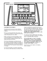
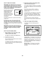
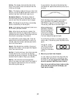
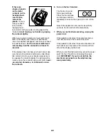
Page 34: ...ht Axle 49 1 Lift Axle 50 1 Right Lift Arm 51 1 Left Lift Arm 52 2 Lift Axle Bushing 53 1 Long Motor Axle 54 1 Short Motor Axle 55 2 Bumper 56 2 8 x 25mm Self tapping Screw 57 6 Upright Bushing 58 2 M10 x 60mm Bolt 59 1 Power Cord 60 1 Upright Wire 61 1 Eddy Mechanism 62 4 M6 x 50mm Screw 63 1 Frame Axle 64 4 Frame Bushing 65 1 Latch Bracket Axle 66 1 Latch Bracket Spring 67 1 Latch Button 68 1 Bu...

Page 35: ... Spring 119 2 Medium Snap Ring 120 14 Mushroom Fastener Screw 121 2 Latch Insert 122 1 3 8 x 1 2 Flange Screw 123 2 Latch Housing 124 4 M4 x 42mm Screw 125 1 Power Switch 126 8 M8 x 25mm x 1 5mm Washer 127 2 M8 x 30mm Screw 128 4 M8 x 25mm Screw 129 2 Outer Sleeve Bushing 130 2 Small Snap Ring 131 8 M8 Split Washer 132 2 Short Spring Pin 133 1 Frame Cap 134 2 Inner Sleeve Bushing 135 2 Pulse Wire ...

Page 36: ...9 8 30 35 57 88 48 93 104 126 102 57 35 33 9 57 88 32 31 93 93 93 93 105 105 7 104 104 93 93 11 10 34 34 93 93 93 102 135 5 24 26 25 93 93 57 57 23 131 131 131 102 102 102 131 143 EXPLODED DRAWING A Model No 23897 0 R0812A ...

Page 37: ... 86 86 87 76 73 74 75 75 76 87 71 122 133 93 138 78 61 70 60 38 16 39 40 17 16 17 39 40 40 120 120 120 109 125 59 4 37 37 41 41 100 93 93 77 85 27 142 28 20 124 124 18 19 124 124 93 93 93 69 72 142 EXPLODED DRAWING B Model No 23897 0 R0812A ...

Page 38: ...41 47 64 64 107 45 44 43 120 120 120 120 120 46 46 108 81 102 83 22 21 52 79 119 50 84 84 119 79 82 82 80 80 51 52 54 81 49 108 67 42 66 3 36 36 55 56 56 55 100 93 93 103 58 58 37 37 93 141 141 93 93 93 93 93 102 83 EXPLODED DRAWING C Model No 23897 0 R0812A ...

Page 39: ...7 127 113 92 130 92 130 113 137 137 138 138 123 123 118 118 121 121 117 117 116 116 90 94 111 126 94 111 111 111 102 128 98 13 140 112 112 129 129 136 136 134 134 139 62 114 98 62 62 12 140 62 140 102 138 132 138 115 115 15 14 140 114 132 EXPLODED DRAWING D Model No 23897 0 R0812A ...

Page 40: ... not extend to freight damage to the product This warranty will automatically be voided if the product is used as a store display model if the product is purchased or transported outside the USA if all instructions in this manual are not followed if the product is abused or improperly or abnormally used or if the product is used for commercial or rental purposes No other warranty beyond that speci...

Reviews: