background image

19

HOW TO TURN ON THE POWER

IMPORTANT: If the treadmill has been exposed to 
cold temperatures, allow it to warm to room tem-
perature before you turn on the power. If you do 
not do this, you may damage the console displays 
or other electrical components.

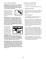
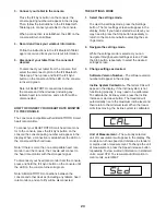
Plug in the power cord 
(see page 17). Next, locate 
the power switch on the 
treadmill frame near the 
power cord. Make sure that 
the switch is in the reset 
position. 

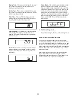
IMPORTANT: The console may feature a demo 
mode, designed to be used if the treadmill is dis-
played in a store. If the displays light as soon as 
you plug in the power cord and press the power 
switch into the reset position, the demo mode is 
turned on. To turn off the demo mode, hold down 
the Stop button for a few seconds. If the displays 
remain lit, see THE SETTINGS MODE on page 23 to 
turn off the demo mode. 

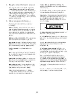
Next, stand on the 
foot rails of the tread-
mill. Find the clip 
attached to the key, 
and slide the clip onto 
the waistband of your 
clothes. Then, insert 
the key into the con-
sole. After a moment, 
the displays will light. 

IMPORTANT: In an emergency, the key can be 
pulled from the console, causing the walking belt 
to slow to a stop. Test the clip by carefully taking 
a few steps backward; if the key is not pulled from 
the console, adjust the position of the clip.

IMPORTANT: Before you use the treadmill, take the 
following steps to ensure that the console shows 
the correct incline level of the treadmill. First, press 
the Incline increase button once. Next, press either 
the Incline decrease button or the lowest Quick 
Incline button to set the treadmill to its lowest set-
ting. When the frame stops moving, the treadmill is 
ready for use.

HOW TO USE THE MANUAL MODE

1.  

 Insert the key into the console. 


 See HOW TO TURN ON THE POWER at the left.

2.


Select the manual mode.


 When the key is inserted, the manual mode will be 
selected. If you have selected a workout, press the 
Manual button. Only zeros should appear in the 
display.

3.


Start the walking belt.


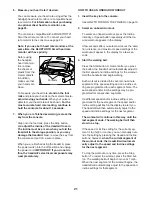
 To start the walking belt, press the Start button or 
one of the numbered Quick Speed buttons. 


 If you press the Start button, the walking belt will 
begin to move at 1 mph. As you exercise, change 
the speed of the walking belt as desired by press-
ing the Speed increase and decrease buttons. 
Each time you press one of the buttons, the speed 
setting will change by 0.2 mph; if you hold down 
the button, the speed setting will change in incre-
ments of 0.5 mph. 


  If you press one of the numbered Quick Speed 
buttons, the walking belt will gradually change 
speed until it reaches the selected speed setting. 
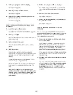
To select a speed setting that includes a decimal—
such as 3.5 mph—press two numbered buttons in 
succession. For example, to select a speed setting 
of 3.5 mph, press the 3 button and then immedi-
ately press the 5 button. Note: This feature will not 
function when the console is set to metric units.


 To stop the walking belt, press the Stop button. 
The time will begin to 

fl

 ash in the display. To restart 

the walking belt, press the Start button or one of 
the numbered Quick Speed buttons. 

Reset

Key

Clip

Summary of Contents for 24860.2

Page 1: ...l before using this equipment Save this manual for future reference To register your product and activate your warranty today go to my nordictrack com For service at any time go to nordictrackservice com Or call 1 800 TO BE FIT 1 800 862 3348 Mon Fri 6 a m 6 p m MT Sat 8 a m 12 p m MT Please do not contact the store ACTIVATE YOUR WARRANTY CUSTOMER CARE Serial Number Decal ...

Page 2: ...ll the telephone number on the front cover of this manual and request a free replacement decal Apply the decal in the location shown Note The decals may not be shown at actual size WARNING DECAL PLACEMENT TABLE OF CONTENTS NORDICTRACK and IFIT are registered trademarks of ICON Health Fitness Inc App Store is a trademark of Apple Inc registered in the U S and other countries Android and Google Play...

Page 3: ...om mended for both men and women Always wear athletic shoes Never use the treadmill with bare feet wearing only stockings or in sandals 13 Plug the power cord into a surge suppressor not included and plug the surge suppres sor into an appropriate outlet see page 17 To avoid overloading the circuit do not plug other electrical devices except for low power devices such as cell phone char gers into t...

Page 4: ... properly assembled See ASSEMBLY on page 9 and HOW TO FOLD AND MOVE THE TREADMILL on page 27 You must be able to safely lift 45 lbs 20 kg to move the treadmill 26 When folding or moving the treadmill make sure that the storage latch is holding the frame securely in the storage position Do not operate the treadmill while it is folded 27 Do not change the incline of the treadmill by placing objects ...

Page 5: ...5 ...
Page 6: ...6 all STANDARD SERVICE PLANS ...

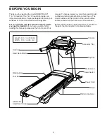
Page 7: ...f this manual To help us assist you note the product model number and serial number before contacting us The model number and the location of the serial number decal are shown on the front cover of this manual Before reading further please familiarize yourself with the parts that are labeled in the drawing below BEFORE YOU BEGIN Handrail Heart Rate Monitor Console Key Clip Accessory Tray Power Swi...

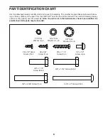
Page 8: ...l The number following the key number is the quantity used for assembly Note If a part is not in the hardware kit check to see whether it is preattached Extra parts may be included 5 16 x 3 Screw 28 4 10 x 1 1 4 Screw 9 4 1 4 x 1 2 Screw 4 4 3 8 Star Washer 13 8 5 16 Star Washer 11 6 8 x 1 2 Silver Screw 10 1 10 Star Washer 5 4 3 8 x 2 3 8 Screw 7 4 3 8 x 1 3 4 Screw 62 2 3 8 x 1 1 4 Screw 63 2 8 ...

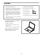
Page 9: ... parts are marked L or Left and right parts are marked R or Right To identify small parts see page 8 Assembly requires the following tools the included hex keys one Phillips screwdriver one adjustable wrench To avoid damaging parts do not use power tools ASSEMBLY 1 Go to my nordictrack com on your computer and register your product activates your warranty saves you time if you ever need to contact...

Page 10: ...er Screw 10 6 90 10 90 A 2 81 77 C B D 2 Make sure that the power cord is unplugged Remove the tie securing the Upright Wire 81 to the front of the Base 6 Next identify the Right Upright 90 Have a second person hold the Right Upright near the Base 6 See the inset drawing Tie the wire tie A in the Right Upright 90 securely around the end of the Upright Wire 81 Then insert the Upright Wire into the ...

Page 11: ... four 3 8 Star Washers 13 as shown do not fully tighten the Screws yet Attach the Left Upright not shown in the same way Note There are no wires on the left side 4 63 62 6 13 13 90 7 13 5 Identify the Left and Right Base Covers 82 83 Slide the Left Base Cover onto the Left Upright 89 and slide the Right Base Cover onto the Right Upright 90 Do not press the Base Covers into place yet 82 90 83 5 89 ...

Page 12: ...rt both Screws and then tighten them Make sure not to pinch the Upright Wire 81 Attach the other Handrail not shown to the Left Upright not shown in the same way Note There are no wires on the left side 11 81 84 28 6 90 64 31 F F 7 7 Set the Console Base 64 face down on a soft surface to avoid scratching the Console Base Remove and discard the two indicated screws F Then remove the Pulse Crossbar ...

Page 13: ...nd person hold the con sole assembly G near the Handrail 84 Connect the ground wire H from the console assembly G to the Console Ground Wire 58 on the Pulse Crossbar 31 See the inset drawing Connect the Upright Wire 81 to the console wire I The connec tors should slide together easily and snap into place If they do not turn one connector and try again IF YOU DO NOT CONNECT THE CONNECTORS PROPERLY ...

Page 14: ... the console assembly G to the brack ets on the Handrails 84 with four 1 4 x 1 2 Screws 4 do not tighten the Screws yet 11 Attach the Pulse Crossbar 31 to the console assembly G with six 8 x 5 8 Screws 1 start all six Screws and then tighten them Do not overtighten the Screws Firmly tighten the four 1 4 x 1 2 Screws 4 10 11 90 G G 4 4 4 4 81 84 31 1 1 84 ...

Page 15: ...tch Crossbar to the brackets K on the Frame 56 with the two 5 16 x 3 4 Screws 8 that you just removed and two 5 16 Star Washers 11 56 41 J 8 8 K K 11 11 6 26 23 34 L 13 13 Remove the 5 16 Nut 34 and the 5 16 x 1 3 4 Bolt 23 from the bracket on the Base 6 Next orient the Storage Latch 26 as shown Attach the lower end of the Storage Latch 26 to the bracket on the Base 6 with the 5 16 x 1 3 4 Bolt 23...

Page 16: ...ill If there are sheets of plastic on the treadmill decals remove the plastic To protect the floor or carpet place a mat under the treadmill To avoid damage to the console keep the treadmill out of direct sunlight Keep the included hex key in a secure place the hex key is used to adjust the walking belt see pages 29 Note Extra hardware may be included 15 Firmly tighten the four 3 8 x 2 3 8 Screws ...

Page 17: ...e surge suppressor into an appropriate outlet that is properly installed and grounded in accordance with all local codes and ordinances The outlet must be on a nominal 120 volt circuit capable of carrying 15 or more amps To avoid overloading the circuit do not plug other electrical devices except for low power devices such as cell phone chargers into the surge suppressor or into an outlet on the s...

Page 18: ...ck your workout information You can even listen to your favorite workout music or audio books with the console s sound system while you exercise To turn on the power see page 19 To use the man ual mode see page 19 To use an onboard workout see page 21 To use a custom focus weight loss workout see page 22 To connect your tablet to the console see page 22 To connect your heart rate monitor to the co...

Page 19: ...ess the Incline increase button once Next press either the Incline decrease button or the lowest Quick Incline button to set the treadmill to its lowest set ting When the frame stops moving the treadmill is ready for use HOW TO USE THE MANUAL MODE 1 Insert the key into the console See HOW TO TURN ON THE POWER at the left 2 Select the manual mode When the key is inserted the manual mode will be sel...

Page 20: ...PH Your speed in miles per hour or kilometers per hour To change the unit of measurement press the ST MET button Time When the manual mode is selected the elapsed time When an onboard workout is selected the time remaining in the workout Vertical Distance VRT FT or VRT M The distance you have walked or run in vertical feet or vertical meters Press the Next Display button repeatedly to view the des...

Page 21: ...E POWER on page 19 2 Select an onboard workout To select an onboard workout press the Incline Intensity or Speed button repeatedly until the de sired workout appears in the display A few seconds after you select a workout the dura tion distance and maximum speed settings of the workout will appear in the display for a few sec onds 3 Start the walking belt Press the Start button A moment after you ...

Page 22: ...s factors such as your weight 5 Follow your progress with the displays See step 5 on page 20 The display will show the time or calories remaining instead of the elapsed time 6 Measure your heart rate if desired See step 6 on page 21 7 When you are finished exercising remove the key from the console See step 7 on page 21 HOW TO CONNECT YOUR TABLET TO THE CONSOLE The console supports BLUETOOTH conne...

Page 23: ... monitor from the console press and hold the iFit Sync button on the console until the LED on the console turns solid green Note All BLUETOOTH connections between the console and other devices including any tablets heart rate monitors and so forth will be disconnected THE SETTINGS MODE 1 Select the settings mode To select the settings mode press the Settings button The first settings screen will a...

Page 24: ...console features a demo mode designed to be used if the treadmill is displayed in a store If the demo mode is turned on the console will not turn off and the display will not be reset when you finish exercis ing Press the Speed increase button repeatedly to select a demo mode option To turn on the demo mode select DON To turn off the demo mode select DOFF 4 Exit the settings mode Press the Setting...

Page 25: ... purchase a tablet holder please see the front cover of this manual HOW TO ADJUST THE CUSHIONING SYSTEM The treadmill features a cushioning system that reduces the impact as you walk or run on the treadmill Remove the key from the console and unplug the power cord To adjust the cushions you may need to place the treadmill in the storage position see HOW TO FOLD THE TREADMILL on page 27 For a more ...

Page 26: ... correct the interference by one or more of the following measures Reorient or relocate the receiving antenna Increase the separation between the equipment and the receiver Connect the equipment into an outlet on a circuit different from that to which the receiver is connected Consult the dealer or an experienced radio TV technician for help FCC CAUTION To assure continued compliance use only shie...

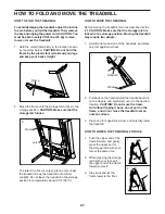
Page 27: ... moving the treadmill fold it as described at the left CAUTION Make sure that the storage latch is locked in the storage position Moving the treadmill may require two people 1 Hold the frame and one of the handrails and place one foot against a wheel 2 Pull back on the handrail until the treadmill will roll on the wheels and carefully move it to the desired location CAUTION Do not move the tread m...

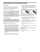
Page 28: ...page 17 Use only a surge suppressor that meets all of the specifications described on page 17 IMPORTANT If the treadmill is connected to an AFCI equipped outlet and your circuit breaker trips repeatedly when the treadmill is used see the front cover of this manual to purchase an arc filter b After the power cord has been plugged in make sure that the key is inserted into the console c Check the po...

Page 29: ...ee the front cover of this manual SYMPTOM The walking belt is not centered between the foot rails The edges of the walking belt should be aligned with the belt alignment marks see the drawing below on the foot rails If necessary follow the instructions below to align the walking belt a IMPORTANT If the walking belt rubs against the foot rails the walking belt may become damaged First remove the ke...

Page 30: ...ic Exercise If your goal is to strengthen your cardiovascular system you must perform aerobic exercise which is activity that requires large amounts of oxygen for prolonged periods of time For aerobic exercise adjust the intensity of your exercise until your heart rate is near the highest number in your training zone WORKOUT GUIDELINES Warming Up Start with 5 to 10 minutes of stretch ing and light...

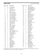
Page 31: ... 1 Walking Belt 46 2 Belt Guide 47 1 Right Rear Foot 48 4 Cable Tie 49 1 Drive Roller Pulley 50 1 Left Inner Base Cover 51 1 Right Inner Base Cover 52 4 3 8 Plastic Bushing 53 2 1 4 x 1 1 4 Screw 54 1 Drive Motor 55 1 Motor Belt 56 1 Frame 57 1 Left Rear Foot 58 1 Console Ground Wire 59 4 Rubber Cushion 60 1 Right Foot Rail 61 1 Idler Roller 62 2 3 8 x 1 3 4 Screw 63 2 3 8 x 1 1 4 Screw 64 1 Conso...

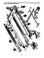
Page 32: ...59 23 43 44 21 14 53 53 46 19 19 46 39 37 34 30 59 34 30 59 20 39 1 1 1 1 39 39 2 57 2 40 40 47 2 2 10 35 35 35 35 35 35 35 35 35 15 10 2 54 55 8 34 25 41 26 34 23 8 11 11 10 85 14 73 24 95 37 37 95 95 37 95 37 95 37 95 EXPLODED DRAWING A Model No 24860 2 R0817A ...

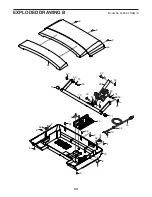
Page 33: ...33 66 10 76 94 68 75 65 72 78 68 68 68 68 2 2 2 2 2 2 2 2 2 2 2 2 67 67 33 29 69 70 16 71 33 33 52 52 74 74 33 71 32 EXPLODED DRAWING B Model No 24860 2 R0817A ...

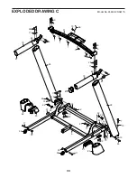
Page 34: ...28 84 87 79 79 81 87 4 9 5 9 5 11 28 1 1 1 1 1 58 10 31 4 17 17 33 77 81 33 6 52 13 13 22 22 52 62 62 3 10 63 82 91 38 83 90 38 91 51 50 13 7 13 63 7 13 13 7 13 12 3 12 77 EXPLODED DRAWING C Model No 24860 2 R0817A ...

Page 35: ...35 2 92 2 86 64 36 27 18 80 88 2 2 2 92 93 93 93 93 93 93 2 2 2 2 EXPLODED DRAWING D Model No 24860 2 R0817A ...

Page 36: ...ial or consequential dam ages arising out of or in connection with the use or performance of the product 2 damages with respect to any economic loss loss of property loss of revenues or profits loss of enjoyment or use or costs of removal or installation or 3 other consequential damages of any kind Some states do not allow the exclusion or limitation of incidental or consequential damages Accordin...

Reviews: