


25
HOW TO USE A PRESET WORKOUT
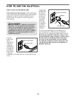
1. Begin pedaling or press any button on the
console to turn on the console.
See HOW TO TURN ON THE POWER on
page 23.
2. Select a preset workout.
If you have selected a workout or the iFit Training
mode, press the Menu button to return to the main
menu.
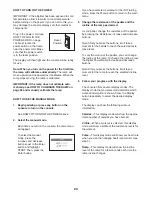
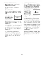
To select a preset
workout, first press the
increase and decrease
buttons next to the Enter
button and highlight
WORKOUTS. Then,
press the Enter button.
Next, press the increase and decrease buttons to
highlight the desired workout category. Then, press
the Enter button.
You can also press the Workouts button repeatedly
to select a workout category or the manual mode.
Press the increase and decrease buttons to high-
light the desired workout subcategory. Then, press
the Enter button.
Press the increase and decrease buttons to
highlight the name of the desired workout. The
duration, the maximum rpm (pedaling pace), the
maximum resistance level, and a profile of the
resistance levels of the workout will appear in the
right side of the display. Then, press the Enter
button.
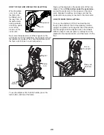
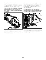
3. Begin pedaling to start the workout.
Each workout is divided into one-minute segments.
One resistance level and one target rpm (pedaling
pace) are programmed for each segment. Note:
The same resistance level and/or target rpm may
be programmed for consecutive segments.
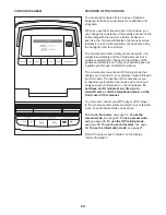
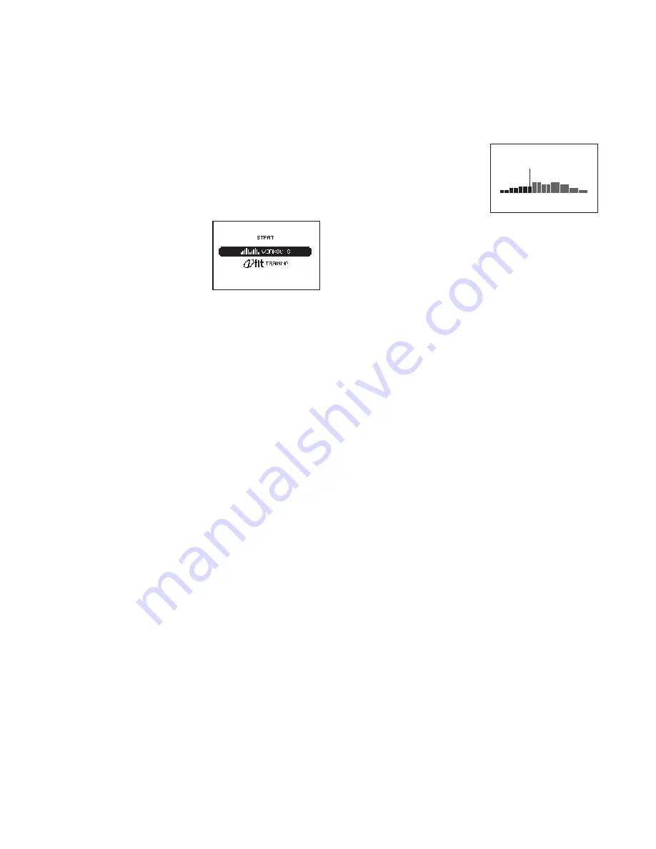
The workout profile will
show your progress.
The flashing segment
of the profile represents
the current segment of
the workout. The height
of the flashing segment
indicates the resistance level for the current
segment.
When the first segment of the workout ends, the
resistance level and the target rpm for the second
segment will appear in the display for a few sec-
onds to alert you. The next segment of the profile
will begin to flash, and the pedals will automatically
adjust to the resistance level for the next segment.
As you exercise, you will be prompted to keep your
pedaling pace (rpm) near the target rpm for the cur-
rent segment. When the word FASTER appears in
the display, increase your pedaling pace. When the
word SLOWER appears, decrease your pedaling
pace. When no words appear, maintain your cur-
rent pedaling pace.
IMPORTANT: The target rpm is intended only to
provide motivation. Your actual pedaling pace
(rpm) may be slower than the target rpm. Make
sure to pedal at a pace that is comfortable for
you.
Current Segment
Summary of Contents for 29826.3
Page 5: ...5...


