background image

30

EXERCISE GUIDELINES

These guidelines will help you to plan your exercise 

program. For detailed exercise information, obtain a 

reputable book or consult your physician. Remember, 

proper nutrition and adequate rest are essential for 

successful results. 

EXERCISE INTENSITY

Whether your goal is to burn fat or to strengthen your 

cardiovascular system, exercising at the proper inten-

sity is the key to achieving results. You can use your 

heart rate as a guide to find the proper intensity level. 

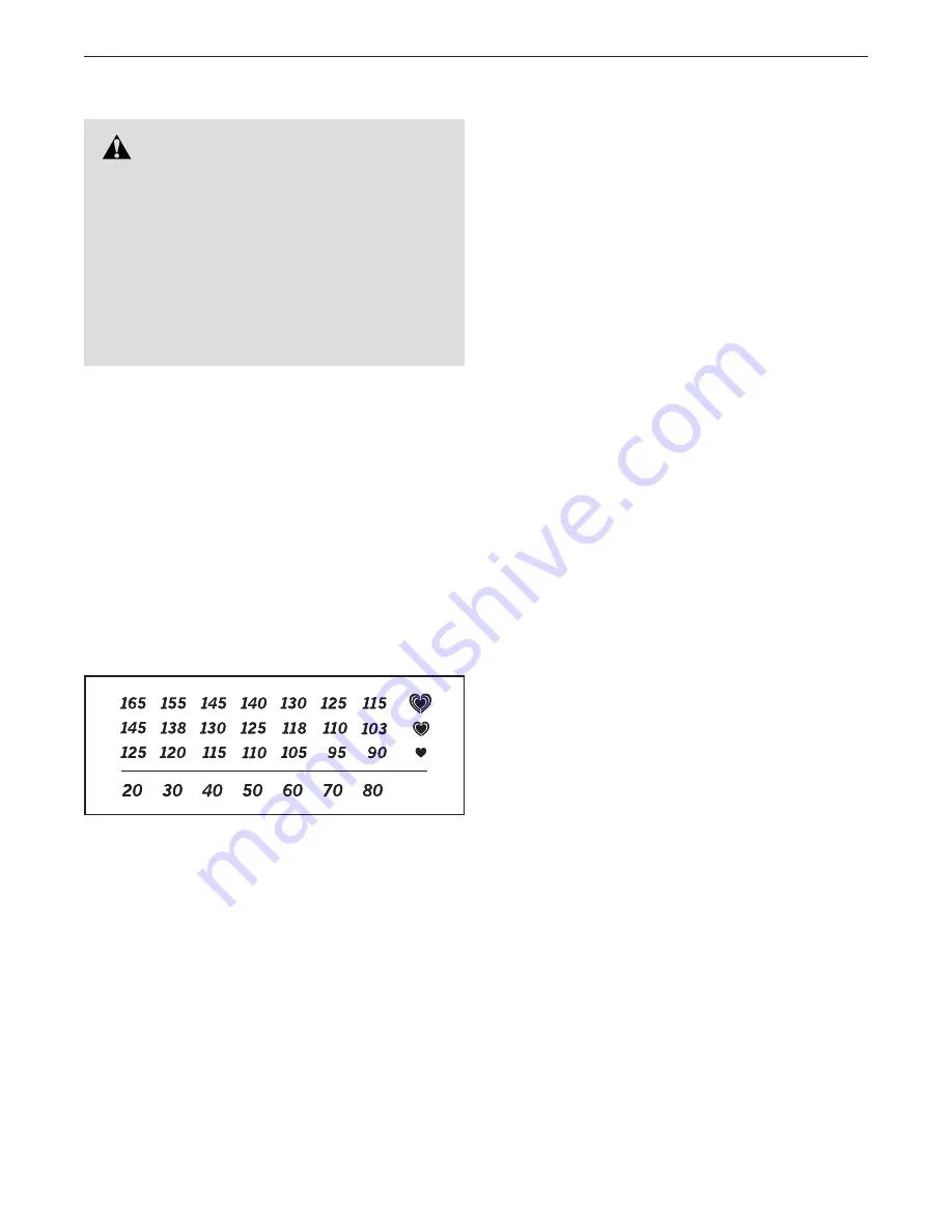
The chart below shows recommended heart rates for 

fat burning and aerobic exercise.

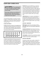
To find the proper intensity level, find your age at the 

bottom of the chart (ages are rounded off to the near-

est ten years). The three numbers listed above your 

age define your “training zone.” The lowest number is 

the heart rate for fat burning, the middle number is the 

heart rate for maximum fat burning, and the highest 

number is the heart rate for aerobic exercise.

Burning Fat

—To burn fat effectively, you must exer-

cise at a low intensity level for a sustained period of 

time. During the first few minutes of exercise, your 

body uses carbohydrate calories for energy. Only after 

the first few minutes of exercise does your body begin 

to use stored fat calories for energy. If your goal is to 

burn fat, adjust the intensity of your exercise until your 

heart rate is near the lowest number in your training 

zone. For maximum fat burning, exercise with your 

heart rate near the middle number in your training 

zone.

Aerobic Exercise

—If your goal is to strengthen your 

cardiovascular system, you must perform aerobic 

exercise, which is activity that requires large amounts 

of oxygen for prolonged periods of time. For aerobic 

exercise, adjust the intensity of your exercise until your 

heart rate is near the highest number in your training 

zone. 

WORKOUT GUIDELINES

Warming Up

—Start with 5 to 10 minutes of stretch-

ing and light exercise. A warm-up increases your body 

temperature, heart rate, and circulation in preparation 

for exercise. 

Training Zone Exercise

—Exercise for 20 to 30 min-

utes with your heart rate in your training zone. (During 

the first few weeks of your exercise program, do not 

keep your heart rate in your training zone for longer 

than 20 minutes.) Breathe regularly and deeply as you 

exercise ; never hold your breath. 

Cooling Down

—Finish with 5 to 10 minutes of stretch-

ing. Stretching increases the flexibility of your muscles 

and helps to prevent post-exercise problems.

EXERCISE FREQUENCY

To maintain or improve your condition, complete three 

workouts each week, with at least one day of rest 

between workouts. After a few months of regular exer-

cise, you may complete up to five workouts each week, 

if desired. Remember, the key to success is to make 

exercise a regular and enjoyable part of your everyday 

life.

    WARNING:

 Before beginning this 

or any exercise program, consult your physi-

cian. This is especially important for persons 

over age 35 or persons with pre-existing 

health problems.

The heart rate monitor is not a medical device. 

Various factors may affect the accuracy of 

heart rate readings. The heart rate monitor is 

intended only as an exercise aid in determin-

ing heart rate trends in general.

Summary of Contents for 29826.3

Page 1: ...n this manual before using this equipment Keep this manual for future reference www nordictrack com To register your product and activate your warranty today contact Customer Service Call toll free 1...

Page 2: ...decal Apply the decal in the loca tion shown Note The decal s may not be shown at actual size 25886 25886 25886 25887 25887 2 WARNING DECAL PLACEMENT 2 IMPORTANT PRECAUTIONS 3 BEFORE YOU BEGIN 7 PART...

Page 3: ...ptical at all times 9 When connecting the power cord plug the power cord into a grounded circuit To avoid overloading the circuit do not plug other electrical devices except for low power devices such...

Page 4: ...e your pedaling speed in a controlled way 19 Keep your back straight while using the ellip tical do not arch your back 20 Over exercising may result in serious injury or death If you feel faint or if...

Page 5: ...5...

Page 6: ...ver 100 authorized repair centers Highly trained repair technicians A national toll free repair hotline Simple repair claim procedure No claim forms Easy enrollment Fast efficient repair anywhere in C...

Page 7: ...help us assist you note the product model number and serial number before contacting us The model number and the location of the serial number decal are shown on the front cover of this manual Before...

Page 8: ...Screw 111 4 PART IDENTIFICATION CHART Use the drawings below to identify the small parts needed for assembly The number in parentheses below each drawing is the key number of the part from the PART L...

Page 9: ...see page 8 In addition to the included tool s assembly requires the following tool s one Phillips screwdriver one rubber mallet Assembly may be easier if you have a set of wrenches To avoid damaging p...

Page 10: ...tabilizer 4 press the Latch Button 67 and lower the Rear Stabilizer and the Folding Frame 2 to the floor 4 2 100 Handle 2 67 3 Orient the Front Stabilizer 3 so that the indicated hole is facing the pi...

Page 11: ...ar the Main Frame 1 Locate the wire tie in the Upright 5 Tie the lower end of the wire tie to the Wire Harness 60 Next pull the upper end of the wire tie until the Wire Harness is routed through the U...

Page 12: ...and to two Wave Washers 118 Tip Avoid damaging the Wire Harness 60 Insert the Upright Axle 48 through the Upright 5 and center it Slide a Wave Washer 118 onto each side of the Upright Axle Next identi...

Page 13: ...l Arm 12 and the Right Pedal 14 Then tighten the two M6 x 12mm Screws 111 Attach the Left Pedal not shown to the Left Pedal Arm not shown assembly in the same way 14 88 12 111 112 112 62 8 Apply greas...

Page 14: ...er 32 on the right side of the Ramp 130 See drawing 9b Pull upward on the Latch 50 on the Right Pedal Arm 12 Press the Right Pedal Arm 12 onto the right Pedal Arm Sleeve 46 Make sure that the Right Pe...

Page 15: ...sing a second hex key tighten another M8 x 35mm Screw 92 a Small Axle Cover 56 and an M8 Washer 95 into the other end of the Link Arm Axle 114 Tip Avoid damaging the Small Axle Cover when tightening t...

Page 16: ...102 Slide the Top Cover 27 downward and press it into the Right and Left Frame Covers 21 22 13 Identify the Right Handlebar 10 and orient it as shown Have a second person hold the Right Handlebar 10 n...

Page 17: ...80 through the Upright 5 into the upper end of the Console 33 Make sure to start the Screws into the indicated upper holes in the Console Do not tighten the M4 x 19mm Screws 80 yet You will tighten t...

Page 18: ...the elliptical 24 25 17 Orient the Front Upright Cover 24 as shown Attach the Front Upright Cover 24 around the Upright 5 by pressing it into the Rear Upright Cover 25 16 Attach the lower end of the...

Page 19: ...The lug or wire extending from the adapter must be connected with a metal screw to a permanent ground such as a properly grounded outlet box cover Some 2 pole receptacle outlet box covers are not gro...

Page 20: ...xt pull the magnets on the pedal arms off the han dlebars Then lift the latches under the pedal arms and set the pedal arms on the sleeves on the crank arms Release the latches and make sure that the...

Page 21: ...ismount the elliptical wait until the pedals come to a complete stop Note The elliptical does not have a free wheel the pedals will continue to move until the flywheel stops When the pedals are statio...

Page 22: ...des you through an effective workout The console also features an iFit training mode that allows you to connect to your wireless network through an iFit module The optional iFit module allows you to d...

Page 23: ...If you have selected a workout or the iFit Training mode press the Menu button to return to the main menu 3 Change the resistance of the pedals and the incline of the ramp as desired As you pedal chan...

Page 24: ...ipping the contacts tightly When your pulse is detected your heart rate will appear in the display For the most accurate heart rate reading hold the contacts for at least 15 seconds If the display doe...

Page 25: ...rt the workout Each workout is divided into one minute segments One resistance level and one target rpm pedaling pace are programmed for each segment Note The same resistance level and or target rpm m...

Page 26: ...call the tele phone number on the front cover of this manual To select the iFit training mode first insert the iFit mod ule into the console Press the Menu button and then press the increase and decr...

Page 27: ...l the bullet appears next to the word CONTRAST Press the Enter button and then press the increase and decrease buttons repeatedly to select the desired contrast level Press the Enter button again to s...

Page 28: ...s it calibrates When the ramp stops moving the ramp is calibrated Then press the Workouts button repeatedly to exit the test mode HOW TO ADJUST THE REED SWITCH If the console does not display correct...

Page 29: ...13 and then lift the Left Pedal Arm off the left Pedal Arm Sleeve 46 See EXPLODED DRAWING C on page 35 Remove the M4 x 16mm Round Head Screws 84 and the M4 x 42mm Screws 83 from the Right and Left Sh...

Page 30: ...c Exercise If your goal is to strengthen your cardiovascular system you must perform aerobic exercise which is activity that requires large amounts of oxygen for prolonged periods of time For aerobic...

Page 31: ...xle 49 2 Latch Housing 50 2 Latch 51 2 Large Latch Spring 52 2 Latch Insert 53 4 Long Latch Spring 54 16 Arm Leg Bushing 55 4 M4 x 16mm Flat Head Screw 56 6 Small Axle Cover 57 2 Upright Bushing 58 2...

Page 32: ...et 117 1 Left Pedal Pad 118 2 Wave Washer 119 1 Power Cord 120 1 Control Board 121 2 M8 x 25mm Screw 122 1 3 8 x 1 Flange Screw 123 4 Double Tree Fastener 124 1 Control Board Bracket 125 1 Transformer...

Page 33: ...113 58 47 46 32 101 32 101 121 95 113 47 46 58 54 54 127 106 49 51 52 50 53 128 43 92 114 56 95 114 56 54 54 54 56 5 24 109 95 56 27 28 13 112 111 62 30 31 31 28 30 111 12 62 112 31 31 62 111 112 62 1...

Page 34: ...0 72 39 86 100 98 107 38 61 115 116 2 37 4 37 122 39 107 1 64 41 16 100 36 36 126 3 126 16 134 41 41 64 60 91 135 145 107 133 131 130 29 29 29 29 29 85 132 132 132 108 40 137 45 141 139 136 104 143 10...

Page 35: ...35 21 84 84 84 20 84 83 84 84 19 83 18 83 83 22 84 84 84 84 23 17 29 29 79 17 29 29 79 29 EXPLODED DRAWING C Model No 29826 3 R1212B...

Page 36: ...inimal trip charge This warranty does not extend to freight damage to the product This warranty will automatically be voided if the product is used as a store display model if all instructions in this...

Reviews: