background image

10

OPERATION AND ADJUSTMENT

THE PRE-LUBRICATED WALKING BELT

Your treadmill features a walking belt coated with high-

performance lubricant.

IMPORTANT: Never apply sil-

icone spray or other substances to the walking

belt or the walking platform. Such substances will

deteriorate the walking belt and cause excessive

wear.

HOW TO PLUG IN THE POWER CORD

Your treadmill, like any other type of sophisticated

electronic equipment, can be seriously damaged by

sudden voltage changes in your homeʼs power.

Voltage surges, spikes, and noise interference can

result from weather conditions or from other appliances

being turned on or off.

To decrease the possibility of

your treadmill being damaged, always use a surge

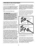
suppressor with your treadmill (see drawing 1 at

the right). To purchase a surge suppressor call the

telephone number on the front cover of this man-

ual.

Use only a single-outlet surge suppressor that is

UL 1449 listed as a transient voltage surge sup-

pressor (TVSS). The surge suppressor must have a

UL suppressed voltage rating of 400 volts or less

and a minimum surge dissipation of 450 joules.

The surge suppressor must be electrically rated for

120 volts AC and 15 amps. There must be a moni-

toring light on the surge suppressor to indicate

whether it is functioning properly. Failure to use a

properly functioning surge suppressor could result

in damage to the control system of the treadmill. If

the control system is damaged, the walking belt

may change speed, accelerate, or stop unexpect-

edly, which may result in a fall and serious injury.

This product must be grounded.

If it should malfunc-

tion or break down, grounding provides a path of least

resistance for electric current to reduce the risk of elec-

tric shock. This product is equipped with a cord having

an equipment-grounding conductor and a grounding

plug.

Plug the power cord into a surge suppressor,

and plug the surge suppressor into an appropriate

outlet that is properly installed and grounded in

accordance with all local codes and ordinances.

IMPORTANT: The treadmill is not compatible with

GFCI-equipped outlets.

This product is for use on a nominal 120-volt circuit,

and has a grounding plug that looks like the plug illus-

trated in drawing 1 below. A temporary adapter that

looks like the adapter illustrated in drawing 2 may be

used to connect the surge suppressor to a 2-pole

receptacle as shown in drawing 2 if a properly

grounded outlet is not available.

The temporary adapter should be used only until a

properly grounded outlet (drawing 1) can be installed

by a qualified electrician.

The green-colored rigid ear, lug, or the like extending

from the adapter must be connected to a permanent

ground such as a properly grounded outlet box cover.

Whenever the adapter is used it must be held in place

by a metal screw.

Some 2-pole receptacle outlet box

covers are not grounded. Contact a qualified elec-

trician to determine if the outlet box cover is

grounded before using an adapter.

DANGER:

Improper connection

of the equipment-grounding conductor can

result in an increased risk of electric shock.

Check with a qualified electrician or service-

man if you are in doubt as to whether the

product is properly grounded. Do not modify

the plug provided with the product—if it will

not fit the outlet, have a proper outlet

installed by a qualified electrician.

1

2

Grounded Outlet Box

Grounded Outlet Box

Grounding Plug

Surge Suppressor

Surge Suppressor

Grounding Pin

Adapter

Lug

Metal Screw

Grounded Outlet

Grounding Pin

Summary of Contents for 30849.2

Page 1: ...er Decal Model No 30849 2 Serial No Write the serial number in the space above for reference QUESTIONS If you have questions or if parts are damaged or missing PLEASE CONTACT OUR CUSTOMER SERVICE DEPARTMENT DIRECTLY CALL TOLL FREE 1 888 936 4266 Mon Fri 8 00 until 17 00 ET excluding holidays OR E MAIL US customerservice iconcanada ca www nordictrack com ...

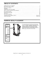
Page 2: ...RAWING 28 ORDERING REPLACEMENT PARTS Back Cover LIMITED WARRANTY Back Cover NordicTrack is a registered trademark of ICON IP Inc 2 This drawing shows the location s of the warning decal s If a decal is missing or illegible call the telephone number on the front cover of this manual and request a free replacement decal Apply the decal in the location shown Note The decal s may not be shown at actua...

Page 3: ...ppliance should be on the same circuit Do not use an extension cord 12 Use only a single outlet surge suppressor that meets all of the specifications described on page 10 To purchase a surge suppressor call the telephone number on the front cover of this manual 13 Failure to use a properly functioning surge suppressor could result in damage to the con trol system of the treadmill If the control sy...

Page 4: ...ays remove iFit cards from the iFit slot when you are not using them 25 Inspect and properly tighten all parts of the treadmill regularly 26 Never insert or drop any object into any opening in the treadmill 27 DANGER Always unplug the power cord immediately after use before cleaning the treadmill and before performing the main tenance and adjustment procedures de scribed in this manual Never remov...

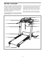
Page 5: ...g the treadmill If you have questions after read ing this manual please see the front cover of this man ual To help us assist you note the product model number and serial number before contacting us The model number and the location of the serial number decal are shown on the front cover of this manual Before reading further please look at the drawing below and familiarize yourself with the labele...

Page 6: ...ded hex key a Phillips screwdriver and wire cutters For help identifying the assembly hardware see the drawings below The number in parentheses below each drawing is the key number of the part from the PART LIST near the end of this manual The number following the parentheses is the quantity needed for assembly Note If a part is not in the parts bag check to see if it has been preassembled To avoi...

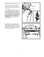
Page 7: ... should slide together easily and snap into place If they do not turn one connector and try again IF THE CONNECTORS ARE NOT CON NECTED PROPERLY THE CONSOLE MAY BE DAMAGED WHEN THE POWER IS TURNED ON Then insert the connectors into the right Upright 20 7 2 Console Assembly Console Wire 3 Carefully set the console assembly on the Uprights 20 as shown Make sure that no wires are pinched Attach the co...

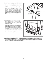
Page 8: ...age position and make sure that the latch pin is engaged as de scribed on page 21 Position the Base Plate 75 on the treadmill as shown Attach the Base Plate to the Uprights 20 with three Base Plate Bolts 77 Note It may be helpful if a second person tips the tread mill slightly as you tighten the Base Plate Bolts Carefully lower the Walking Platform 15 to the floor as described on page 22 5 6 Make ...

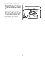
Page 9: ... oriented as shown and is facing the Console Base Attach the receiver to the plastic posts on the Access Door 95 with the two included small screws 3 Make sure that no wires are pinched Reattach the Access Door 95 with the Screw 7 Discard the other wires included with the re ceiver If you purchase the optional chest pulse sensor see page 20 follow the steps below to install the re ceiver included ...

Page 10: ...of least resistance for electric current to reduce the risk of elec tric shock This product is equipped with a cord having an equipment grounding conductor and a grounding plug Plug the power cord into a surge suppressor and plug the surge suppressor into an appropriate outlet that is properly installed and grounded in accordance with all local codes and ordinances IMPORTANT The treadmill is not c...

Page 11: ...e 8 week Weight Loss program or train for a long distance run with the Marathon program iFit pro grams automatically control the treadmill while the voice of a personal trainer coaches you and motivates you through every step of your workout iFit cards are available separately To purchase iFit cards at any time go to www iFit com or call the telephone num ber on the front cover of this manual iFit...

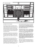
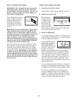
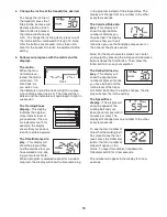
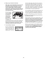
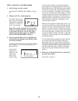
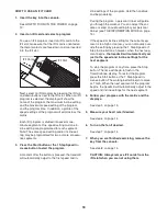
Page 12: ...s not pulled from the console adjust the posi tion of the clip HOW TO USE THE MANUAL MODE 1 Insert the key into the console See HOW TO TURN ON THE POWER at the left 2 Select the manual mode When the key is inserted the man ual mode will be selected If a pro gram has been selected reselect the manual mode by pressing the Program Select button repeatedly until a track appears in the matrix 3 Start t...

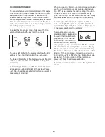
Page 13: ...elected except for a custom program the display will show the time remaining in the program instead of the elapsed time The display will change from one number to the other every few seconds The Calories Pulse dis play This display will show the approximate number of calories you have burned The display will also show your heart rate when you use the handgrip pulse sensor or the optional chest pul...

Page 14: ...he word HIGH will appear in the matrix To select the auto mode press the button again the word AUTO will appear in the matrix When the auto mode is selected the speed of the fan will au tomatically increase and decrease as the speed of the walking belt increases and decreases To turn off the fan press the Fan button again the word OFF will appear in the matrix Note If the fan is left on when the w...

Page 15: ...s the speed setting for the current segment At the end of each segment a series of tones will sound and the next segment of the profile will begin to flash If a differ ent speed or incline setting is programmed for the next segment the speed or incline setting will ap pear in the display to alert you The workout will continue in this way until the last segment of the profile flashes in the display...

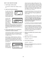
Page 16: ...the matrix To program a speed setting and an incline setting for the first segment simply adjust the speed and incline of the treadmill as de sired by pressing the Speed and Incline buttons Every few times a Speed button is pressed an ad ditional indicator will appear or disappear in the current segment column When the first segment of the program ends a se ries of tones will sound and the current...

Page 17: ...ine setting will flash in the displays to alert you When the first segment is completed all speed set tings will move one column to the left The speed setting for the second segment will then be shown in the flashing current segment column and the treadmill will automatically adjust to the speed and incline settings for the second segment The program will continue in this way until the speed setti...

Page 18: ...ettings of the program Hold the handrails and begin walking During the program a personal trainer will guide you through the workout You can adjust the vol ume or select an audio setting for your personal trainer see THE INFORMATION MODE on page 19 If the speed or incline setting for the current seg ment is too high or too low you can manually over ride the setting by pressing the 1 Step Speed or ...

Page 19: ...u use an iFit card a personal trainer will guide you through your workouts and give detailed instruc tions if P is selected as the audio setting If you turn off the P setting your personal trainer will simply guide you through your iFit workouts Press the 1 Step Incline decrease button to change the audio setting You can adjust the volume of the personal trainer audio 0 through 5 by pressing the 1...

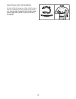
Page 20: ...SE SENSOR An optional chest pulse sensor offers hands free oper ation as it monitors your heart rate during your work outs To purchase the optional chest pulse sensor call the telephone number on the front cover of this manual ...

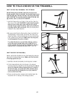
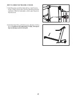
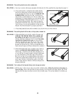
Page 21: ...he plate passes the pin on the latch knob Release the latch knob Make sure that the plate is resting against the pin as shown To protect the floor or carpet from damage place a mat under the treadmill Keep the treadmill out of direct sunlight Do not leave the treadmill in the stor age position in temperatures above 85 F 30 C HOW TO MOVE THE TREADMILL Before moving the treadmill convert the treadmi...

Page 22: ...nd as shown Using your left hand pull the latch knob to the left and hold it Pivot the frame down until it is past the pin on the latch knob 2 Hold the frame firmly with both hands and lower it to the floor To decrease the possibility of injury bend your legs and keep your back straight Knob ...

Page 23: ...breaker see the drawing above If the circuit breaker has tripped wait for five minutes and then press the switch to the reset position b Make sure that the power cord is plugged in If the power cord is plugged in unplug it wait for five minutes and then plug it back in c Remove the key from the console Reinsert the key fully into the console d If the treadmill still will not run see the front cove...

Page 24: ...urn the left rear roller bolt clockwise 1 2 of a turn if the walk ing belt has shifted to the right turn the left rear roller bolt counterclockwise 1 2 of a turn Be careful not to overtighten the walking belt Then plug in the power cord insert the key and run the treadmill for a few minutes Repeat until the walking belt is centered b If the walking belt slips when walked on first remove the key an...

Page 25: ... your goal is to strengthen your cardiovascular system you must perform aerobic exer cise which is activity that requires large amounts of oxygen for prolonged periods of time For aerobic ex ercise adjust the intensity of your exercise until your heart rate is near the highest number in your training zone WORKOUT GUIDELINES Warming Up Start with 5 to 10 minutes of stretching and light exercise A w...

Page 26: ... Pad Left 45 1 Belly Pan 46 1 Power Cord Grommet 47 1 Power Cord 48 1 Off Reset Circuit Breaker 49 1 Support Bracket 50 3 Tie Holder 51 1 Releasable Tie 52 10 Plastic Tie 53 4 Support Bracket Screw 54 1 Incline Stop Bracket 55 1 Incline Motor Bolt Upper 56 1 Drive Roller Ground Wire 57 1 Idler Arm Spring 58 1 Idler Arm 59 2 Rear Wheel 60 2 Rear Roller Star Washer 61 2 Spring Washer 62 2 Rear Rolle...

Page 27: ...mmet 102 1 Hole Plug 103 1 Key Clip 4 Black Wire M F 4 White Wire M F 4 Red Wire M F User s Manual Note Specifications are subject to change without notice For information about ordering replacement parts see the back cover of this manual These parts are not illustrated ...

Page 28: ...56 14 12 12 10 8 69 3 44 16 65 15 2 2 5 9 5 9 1 71 6 64 27 36 59 35 2 5 9 62 60 51 87 50 52 49 53 53 18 17 24 7 87 32 11 29 59 28 2 27 32 5 9 62 60 11 61 61 93 28 EXPLODED DRAWING A Model No 30849 2 R1009A ...

Page 29: ...0 84 97 32 91 32 57 63 79 22 21 87 26 30 87 87 87 30 38 32 4 19 4 19 1 14 39 23 87 23 78 43 33 99 99 54 40 41 32 85 46 47 48 45 7 7 85 7 70 7 102 91 7 23 92 101 37 25 86 29 EXPLODED DRAWING B Model No 30849 2 R1009A ...

Page 30: ...77 77 77 75 74 81 82 89 32 13 88 94 96 81 82 32 89 13 88 94 96 81 82 20 76 34 7 72 67 67 72 73 81 82 73 23 90 30 EXPLODED DRAWING C Model No 30849 2 R1009A ...

Page 31: ...100 103 98 42 66 68 66 95 7 7 7 7 7 7 7 7 7 7 7 7 7 7 7 83 23 31 EXPLODED DRAWING D Model No 30849 2 R1009A ...

Page 32: ...ttributable to freight damage abuse misuse improper or abnormal usage or repairs not provided by an ICON authorized service center products used for commercial or rental purposes or products used as store display models No other warranty beyond that specifically set forth above is authorized by ICON ICON is not responsible or liable for indirect special or consequential damages arising out of or i...

Reviews: