
38
1
1
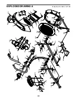
Frame
2
1
Rear Stabilizer Cover
3
1
Ramp
4
1
Upright
5
1
Rear Stabilizer
6
1
Front Stabilizer
7
1
Console
8
1
Front Stabilizer Cover
9
1
Bottom Ramp Cover
10
1
Top Ramp Cover
11
2
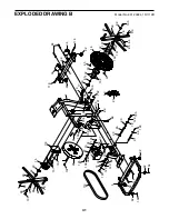
Track
12
1
Left Roller Arm
13
1
Lift Motor
14
1
Left Pedal
15
1
Control Board
16
1
Power Switch
17
1
Power Cord Grommet
18
1
Crank
19
1
Pulley
20
2
Crank Arm
21
2
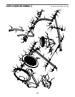
Roller Arm Cap
22
1
Idler
23
4
M3 x 8mm Screw
24
4
M6 x 35mm Screw
25
1
Resistance Motor
26
2
Saddle Bracket
27
2
Lift Motor Bushing
28
1
Eddy Mechanism
29
1
Left Pedal Handle
30
6
Pivot Bushing
31
1
Lift Axle
32
2
Lift Spacer
33
2
Small Snap Ring
34
2
Wheel
35
1
Pivot Axle
36
1
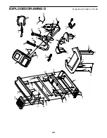
Right Upper Body Leg
37
1
Accessory Tray
38
1
Reed Switch/Wire
39
1
Clamp
40
2
R14 Bearing
41
1
Right Grip
42
1
Long Crank Spacer
43
2
Magnet
44
1
Left Pedal Arm
45
1
Right Roller Arm
46
1
Left Upper Body Leg
47
1
Left Upper Body Arm
48
1
Left Grip
49
1
Right Pedal
50
2
Nylon Insert
51
2
Roller
52
1
Fan Grill
53
6
Axle Cover
54
1
Left Outer Cover
55
1
Left Inner Cover
56
1
Lower Upright Cover
57
4
Roller Arm Bushing
58
1
Right Pedal Arm
59
4
Axle Bushing
60
2
Crank Arm Cover
61
1
Right Upper Body Arm
62
2
Foot
63
1
Right Sensor/Wire
64
4
M6 Washer
65
1
Ramp Axle
66
1
Left Pedal Arm Cover
67
1
Right Outer Cover
68
1
Right Inner Cover
69
1
Left Sensor/Wire
70
4
Pivot Arm Bushing
71
2
Disc
72
2
Ramp Bushing
73
1
Left Front Shield
74
1
Right Front Shield
75
1
Shield Cover
76
1
Left Rear Shield
77
1
Right Rear Shield
78
2
Key
79
6
M6 Locknut
80
1
Rear Upright Cover
81
2
Roller Arm Cover
82
4
M8 x 19mm Screw
83
1
Spacer
84
2
M10 x 90mm Screw
85
2
M6 x 12mm Hex Screw
86
2
M10 x 58mm Hex Bolt
87
1
Right Pedal Arm Cover
88
1
Belt Adjustment Screw
89
1
Pivot Screw
90
4
M10 x 56mm Bolt
91
1
Front Upright Cover
92
4
Leveling Foot
93
13
M4 x 12mm Screw
94
2
Pedal Spring
95
2
Wave Washer
96
4
M8 x 35mm Bolt
97
1
Motor Axle
98
12
M8 x 25mm Washer
99
8
M10 Locknut
100
2
M10 x 138mm Bolt
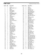
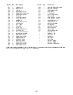
Key No. Qty.
Description
Key No. Qty.
Description
PART LIST
Model No. 831.23924.1 R1112B
Summary of Contents for 831.23924.1
Page 4: ...4...


