
16
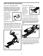
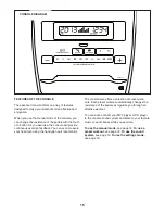
HOW TO USE THE MANUAL MODE
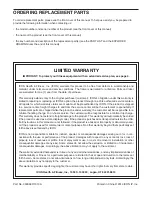
1. Turn on the console.
Press any button or begin pedaling to turn on the
console.
When you turn on the console, the display will turn
on. A tone will then sound and the console will be
ready for use.
2. Select the manual mode.
When you turn on the console, the manual mode
will be selected.
If you have selected a workout, reselect the manual
mode by pressing the Speed button or the Calorie
button repeatedly until a track appears in the center
display.
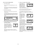
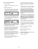
3. Begin pedaling and change the resistance of
the pedals as desired.
As you pedal, change the
resistance of the pedals by
pressing the 1 Step Resistance
increase and decrease but-
tons or by pressing one of the
numbered 1 Step Resistance
buttons.
Note: After you press the buttons, it will take a
moment for the pedals to reach the selected resis-
tance level.
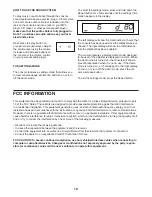
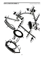
4. Follow your progress with the display.
The left display
–This
display can show the
elapsed time and the
approximate number
of calories you have
burned. The display will
change modes every few seconds.
Note: During a preset workout, the display will
show the time remaining in the workout.
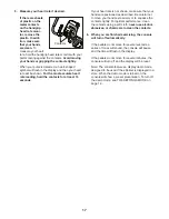
The left display will also show your heart rate
when you use the handgrip heart rate monitor (see
step 5).
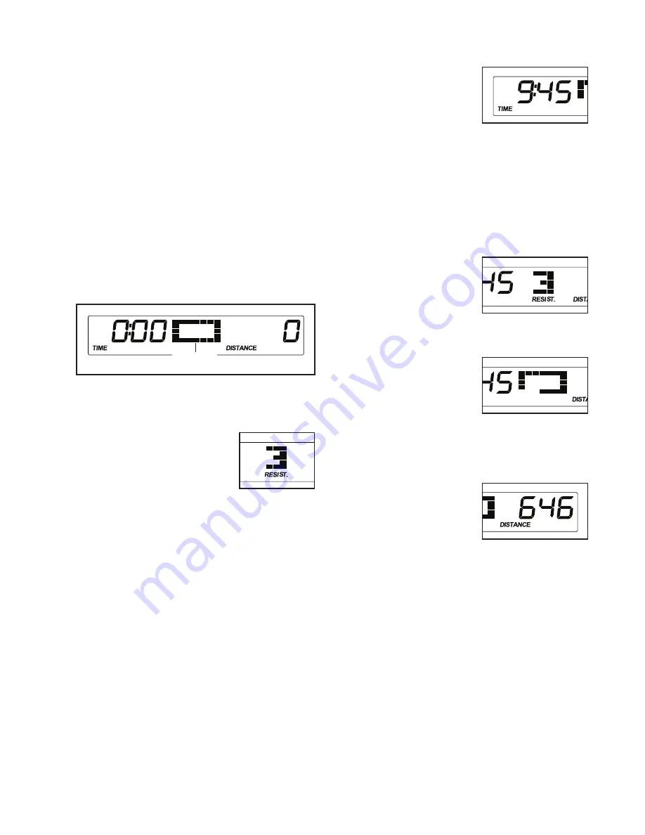
The center display
–
This display will show
the resistance level of
the pedals for a few
seconds each time
the resistance level
changes.
This display will also
show a track represent-
ing 1/4 mile (400 m). As
you exercise, indicators
will appear in succes-
sion around the track
until the entire track appears. The track will then
disappear and the indicators will again begin to
appear in succession.
The right display
–This
display can show the
distance you have
pedaled in total revolu-
tions and your pedaling
speed in revolutions per
minute (rpm). The display will change modes every
few seconds.
Track


