background image

21

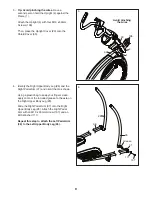
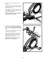
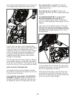
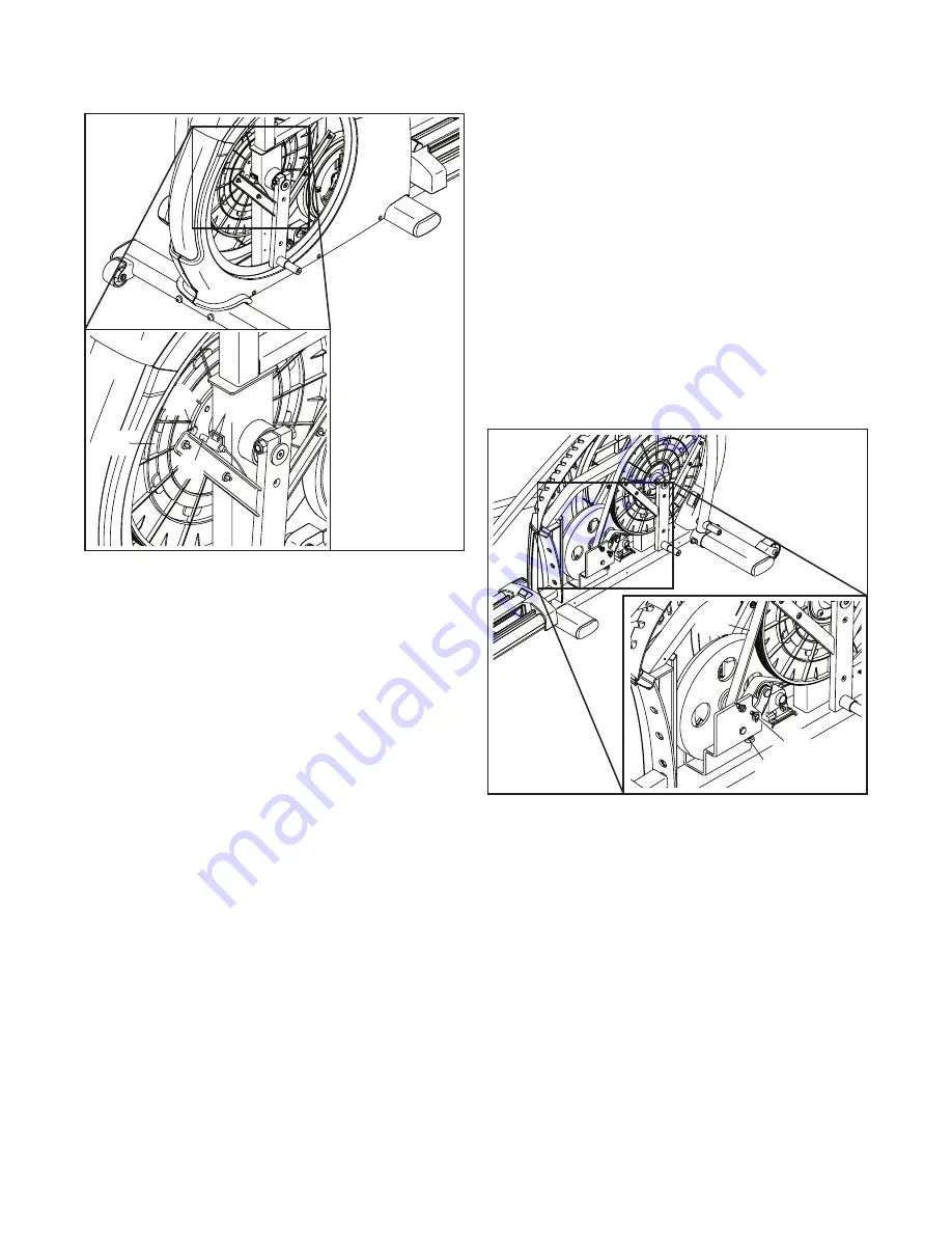
Next, locate the Reed Switch (60). Turn the Pulley (52) 
until a Magnet (86) is aligned with the Reed Switch. 

Loosen, but do not remove, the two indicated M4 x 
16mm Screws (97). Slide the Reed Switch (60) slightly 
closer to or away from the Magnet (86), and then 
retighten the Screws. Then, plug in the power adapter 
and rock the Pulley (52) forward and backward just 
enough that the Magnet passes the Reed Switch 
repeatedly. Repeat these actions until the console 
displays correct feedback. 

When the reed switch is correctly adjusted, unplug the 
power adapter. Reverse the steps above and reattach 
the left disc, the left pedal arm, the left upper body leg, 
and the left roller arm. Then, plug in the power adapter.

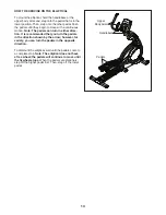
HOW TO ADJUST THE DRIVE BELT

If the pedals slip while you are pedaling, even while 
the resistance is adjusted to the highest level, the drive 
belt may need to be adjusted. 

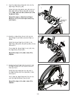
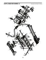
First, unplug the power adapter. See EXPLODED 
DRAWING C on page 27.

 Remove the M8 x 14mm 

Shoulder Screw (89), the Roller Arm Cover (58), and 
the M8 Washer (103) from the Right Roller Arm (39). 

See assembly step 10 on page 11.

 Remove the 

Upper Body Covers A and B (31, 32) from the Right 
Upper Body Arm (25).

See assembly step 9 on page 11.

 Remove the 

Right Upper Body Arm (25) from the Right Upper Body 
Leg (26).

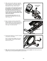
See EXPLODED DRAWING C on page 27 and 
EXPLODED DRAWING B on page 26.

 First, 

remove the Right Roller Arm (39), the Right Pedal 
Arm (37), and the Right Upper Body Leg (26) from the 
elliptical. 

Next, using a flat screwdriver, gently pry off the right 
Disc (29). Then, remove all the Screws (97, 98) from 
the Right and Left Shields (35, 36); 

make sure to note 

the location of each size of Screw.

 Gently remove 

the Right Shield.

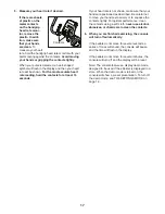
Locate and loosen the Pivot Screw (78). Next, tighten 
the Adjustment Screw (75) until the Drive Belt (113) is 
tight. Then, retighten the Pivot Screw.

When the drive belt is tight, reverse the steps above 
and reattach the right shield, the right disc, the right 
pedal arm, the right upper body leg, and the right roller 
arm. Then, plug in the power adapter.

75

78

113

97

60

86

52

Summary of Contents for 831.23946.1

Page 1: ...rial No Write the serial number in the space above for reference www nordictrack com To register your product and activate your warranty today go to www nordictrackservice com registration For service...

Page 2: ...location shown Note The decal s may not be shown at actual size NORDICTRACK is a registered trademark of ICON IP Inc WARNING DECAL PLACEMENT 2 IMPORTANT PRECAUTIONS 3 BEFORE YOU BEGIN 5 PART IDENTIFI...

Page 3: ...each side To protect the floor or carpet from dam age place a mat under the elliptical 7 Inspect and properly tighten all parts regu larly Replace any worn parts immediately 8 Keep children under age...

Page 4: ...4 all STANDARD SERVICE PLANS...

Page 5: ...please see the front cover of this manual To help us assist you note the product model number and serial number before contacting us The model number and the location of the serial number decal are sh...

Page 6: ...ear the end of this manual The number following the key number is the quantity needed for assembly Note If a part is not in the hardware kit check to see if it has been preassembled Extra parts may be...

Page 7: ...you nish all assembly steps Left parts are marked L or Left and right parts are marked R or Right To identify small parts see page 6 In addition to the included tool s assembly requires the following...

Page 8: ...ch the Front Stabilizer 3 to the Frame 1 with two M10 x 115mm Screws 104 Remove the packing materials from under the front of the Frame 1 1 3 104 4 4 Orient the Upright 4 and the Upright Cover 23 as s...

Page 9: ...y the Right Upper Body Leg 26 and the Right Pedal Arm 37 and orient them as shown Using a plastic bag to keep your fingers clean apply some of the included grease to the axle on the Right Upper Body L...

Page 10: ...an M8 x 18mm Screw 109 and an M8 Washer 103 Repeat this step to attach the Left Upper Body Arm 27 to the Upright 4 7 Apply some of the included grease to an Arm Axle 93 Insert the Arm Axle 93 into the...

Page 11: ...and orient them as shown Attach the Upper Body Cover B 32 to the Right Upper Body Arm 25 with two M4 x 16mm Screws 97 Then press the Upper Body Cover A 31 onto the Upper Body Cover B 32 Repeat this st...

Page 12: ...es Attach the Console 8 to the Upright 4 with four M4 x 16mm Screws 97 Avoid pinching the wires 116 97 117 33 11 PTFE Grease 48 14 15 Make sure that all parts are properly tightened before you use the...

Page 13: ...ired location and then lower it to the floor HOW TO LEVEL THE ELLIPTICAL If the elliptical rocks slightly on your floor during use turn one or both of the leveling feet beneath the rear of the frame u...

Page 14: ...rn in either direc tion It is recommended that you turn the pedals in the direction shown by the arrow however for variety you can turn the pedals in the opposite direction To dismount the elliptical...

Page 15: ...You can even measure your heart rate using the handgrip heart rate monitor The console also offers a selection of preset work outs Each preset workout automatically changes the resistance of the pedal...

Page 16: ...ected resis tance level 4 Follow your progress with the display The left display This display can show the elapsed time and the approximate number of calories you have burned The display will change m...

Page 17: ...our hands are positioned as described Be careful not to move your hands excessively or to squeeze the contacts tightly For optimal performance clean the contacts using a soft cloth never use alcohol a...

Page 18: ...tance level for the next segment will appear in the center display for a few seconds to alert you The resistance of the pedals will then change The target speed for the next segment will appear in the...

Page 19: ...e is turned on a d will appear in the right display To turn on or turn off the demo mode press the vol ume decrease button To exit the settings mode press the Speed button FCC INFORMATION This equipme...

Page 20: ...adapter is needed call the telephone number on the cover of this manual IMPORTANT To avoid damaging the console use only a manufacturer supplied regulated power adapter HOW TO ADJUST THE REED SWITCH I...

Page 21: ...DRAWING C on page 27 Remove the M8 x 14mm Shoulder Screw 89 the Roller Arm Cover 58 and the M8 Washer 103 from the Right Roller Arm 39 See assembly step 10 on page 11 Remove the Upper Body Covers A an...

Page 22: ...c Exercise If your goal is to strengthen your cardiovascular system you must perform aerobic exercise which is activity that requires large amounts of oxygen for prolonged periods of time For aerobic...

Page 23: ...4 Arm Cap 48 2 Roller 49 2 Leg Cap 50 2 Crank Arm 51 1 Large Crank Arm Spacer 52 1 Pulley 53 1 Crank 54 1 Crank Spacer 55 10 Large Bearing 56 2 Leveling Foot 57 4 Roller Arm Bushing 58 2 Roller Arm Co...

Page 24: ...ceptacle 113 1 Drive Belt 114 1 Power Adapter 115 1 Lower Wire 116 1 Upper Wire 117 1 Pulse Wire 118 2 Pulse Grip Back 119 2 Pulse Grip Cap 120 2 Arm Spacer Assembly Tool General White Grease Packet P...

Page 25: ...14 16 18 19 13 15 20 80 80 83 83 83 83 88 88 96 82 90 91 91 94 95 100 100 100 103 103 63 72 97 97 97 97 17 6 5 4 7 9 9 23 65 106 118 97 97 97 97 118 119 119 8 84 28 24 27 31 38 32 40 43 46 48 44 47 97...

Page 26: ...52 51 54 56 59 59 59 53 55 55 60 61 68 67 69 69 85 70 70 71 71 74 74 76 78 79 79 73 73 75 77 81 81 87 87 97 97 97 98 97 97 97 98 99 97 95 95 101 101 34 113 112 116 115 114 105 102 104 104 110 110 29 6...

Page 27: ...NG C 26 30 32 25 24 97 29 31 39 35 37 41 48 45 42 47 47 49 58 57 57 65 64 64 55 55 55 93 120 55 88 85 85 89 92 92 103 103 107 107 107 108 110 103 109 111 111 111 97 98 97 97 97 97 97 97 97 Model No 83...

Page 28: ...This warranty does not extend to freight damage to the product This warranty will automatically be voided if the product is used as a store display model if the product is purchased or transported ou...

Reviews: