background image

24

Inspect and tighten all parts of the elliptical regularly. 
Replace any worn parts immediately. 

To clean the elliptical, use a damp cloth and a small 
amount of mild soap. 

IMPORTANT: To avoid damage 

to the console, keep liquids away from the console 
and keep the console out of direct sunlight.

CONSOLE TROUBLESHOOTING

If the console does not turn on, make sure that the 
power cord is fully plugged in. 

If lines appear in the console display, see HOW TO 
CHANGE CONSOLE SETTINGS on page 22 and 
adjust the contrast level of the display.

If the console does not display your heart rate when 
you hold the handgrip heart rate monitor, or if the dis-
played heart rate appears to be too high or too low, see 
step 5 on page 18.

If the console does not display your heart rate 
when you use the chest heart rate monitor, see 
TROUBLESHOOTING on page 12.

HOW TO GREASE THE ROLLERS

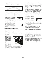
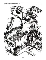
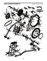
See the EXPLODED DRAWING near the end of this 
manual. If the Large Rollers (51) squeak when mov-
ing on the Tracks (11), apply a small amount of the 
included PTFE grease to a paper towel, and spread 
a thin layer of grease evenly along the Tracks. Then, 
wipe off any excess grease. 

 HOW TO CALIBRATE THE RAMP

If the ramp is not functioning properly, the ramp may 
need to be calibrated. To calibrate the ramp, press and 
hold the Calorie Workouts button for several seconds 
until the test mode appears in the display.

Next, press the Calorie Workouts button again. Then, 
press the Power Ramp increase or decrease button 
to calibrate the ramp. The ramp will move upward and 
downward as it calibrates.

When the ramp stops moving, the ramp is calibrated. 
Then, press the Calorie Workouts button repeatedly to 
exit the calibration mode.

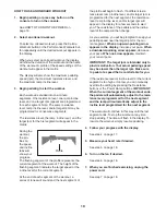
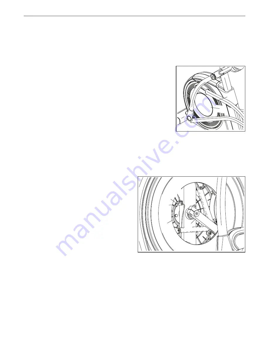
HOW TO ADJUST THE REED SWITCH

If the console does not display correct feedback, the 
reed switch should be adjusted. To adjust the reed 
switch, first 

unplug the power cord.


Next, use a flat 
screwdriver 
and carefully 
pry the left Disc 
Cover (55) off 
the left Disc 
(71).

Next, turn the left Crank Arm (20) until one of the 
Magnets (43) on the Pulley (19) is aligned with the 
Reed Switch (38). Then, loosen, but do not remove, 
the two M4 x 16mm Screws (104), slide the Reed 
Switch slightly closer to or away from the Magnet, and 
retighten the Screws. 

Then, plug in the power cord and turn the left crank 
arm for a moment. Repeat the procedure above, if 
necessary, until the console displays correct feedback. 
Then, reattach the left disc. 

MAINTENANCE AND TROUBLESHOOTING 

55

43

38

19

71

104

20

Summary of Contents for 831.23950.0

Page 1: ...o Write the serial number in the space above for reference www nordictrack com To register your product and activate your warranty today go to www nordictrackservice com registration For service at an...

Page 2: ...l size TABLE OF CONTENTS WARNING DECAL PLACEMENT NORDICTRACK is a registered trademark of ICON IP Inc WARNING DECAL PLACEMENT 2 IMPORTANT PRECAUTIONS 3 BEFORE YOU BEGIN 6 PART IDENTIFICATION CHART 7 A...

Page 3: ...g the power cord into a grounded circuit 10 Do not modify the power cord or use an adapter to connect the power cord to an improper receptacle Keep the power cord away from heated surfaces Do not use...

Page 4: ...4...

Page 5: ...5 UTS all STANDARD SERVICE PLANS...

Page 6: ...r workouts at home more effec tive and enjoyable For your benefit read this manual carefully before you use the elliptical If you have questions after reading this manual please see the front cover of...

Page 7: ...drawings below to identify the small parts needed for assembly The number in parentheses below each drawing is the key number of the part from the PART LIST near the end of this manual The number foll...

Page 8: ...istration provides the following benefits activates your product manufacturer s warranty saves you time if you ever need to contact Customer Care allows us to notify you of upgrades and offers Note If...

Page 9: ...ont of the Frame 1 Have the second per son hold the Frame to prevent it from tipping while you complete this step Identify the Right Front Stabilizer 6 and orient it as shown Attach the Right Front St...

Page 10: ...e Shield Cover 56 downward onto the Rear Shield 75 104 142 56 1 4 8 75 5 Orient the Front Stabilizer Cover 8 as shown and route the Power Cord not shown over the top of the Front Stabilizer Cover Then...

Page 11: ...it so that it is flush with the Right Upper Body Leg 36 Attach the Left Upper Body Arm 47 in the same way 7 Locate the Right Upper Saddle Bracket 121 on the Right Roller Arm 45 Next locate the Lower...

Page 12: ...tures above 122 F 50 C or below 14 F 10 C Do not excessively bend or stretch the sensor when using or storing the heart rate monitor To clean the sensor use a damp cloth and a small amount of mild soa...

Page 13: ...ptacle outlet box covers are not grounded Before using an adapter contact a quali fied electrician to determine whether the outlet box cover is grounded before using an adapter The temporary adapter s...

Page 14: ...ON THE ELLIPTICAL To mount the elliptical hold the upper body arms or the handlebars and step onto the pedal that is in the lower position Then step onto the other pedal Push the pedals until they be...

Page 15: ...ywhere in the world with customizable Google Maps Download training workouts designed to help you reach your personal goals Measure your progress by competing against other users in the iFit community...

Page 16: ...ou exercise To use the manual mode see page 17 To use an onboard workout see page 19 To use a set a goal workout see page 20 To use an iFit workout see page 21 To change console set tings see page 22...

Page 17: ...e distance that you have pedaled in miles or kilometers Pulse This display mode will show your heart rate when you use the handgrip heart rate monitor or the included chest heart rate monitor see step...

Page 18: ...flash in the display each time your heart beats one or two dashes will appear and then your heart rate will be shown For the most accurate heart rate reading hold the contacts for at least 15 seconds...

Page 19: ...sh If a different resis tance level ramp incline level and or target rpm is programmed for the next segment the resistance level ramp incline level and or target rpm will appear in the display for a f...

Page 20: ...ally change the resistance level or the ramp incline level during a calorie goal workout the length of the workout will adjust auto matically to ensure that you meet your calorie goal Note The calorie...

Page 21: ...scheduled Press the Track button to re run a recent iFit work out from your schedule Next press the increase and decrease buttons to select the desired work out Then press the Enter button to start th...

Page 22: ...ected contrast level will appear in the display Press the Power Ramp increase and decrease buttons to adjust the contrast level The following additional settings will be available if an iFit module is...

Page 23: ...equipment does cause harmful interference to radio or television reception which can be determined by turning the equipment off and on try to correct the interference by one or more of the following m...

Page 24: ...any excess grease HOW TO CALIBRATE THE RAMP If the ramp is not functioning properly the ramp may need to be calibrated To calibrate the ramp press and hold the Calorie Workouts button for several seco...

Page 25: ...driver and pry off the Shield Cover 56 and slide it upward Then remove the four M4 x 16mm Screws not shown from the upper and lower ends of the Rear Shield 75 and remove the Rear Shield Then look betw...

Page 26: ...c Exercise If your goal is to strengthen your cardiovascular system you must perform aerobic exercise which is activity that requires large amounts of oxygen for prolonged periods of time For aerobic...

Page 27: ...lles Stretch With one leg in front of the other reach forward and place your hands against a wall Keep your back leg straight and your back foot flat on the floor Bend your front leg lean forward and...

Page 28: ...ight Pedal 50 1 Right Lower Grip 51 4 Large Roller 52 1 Left Lower Grip 53 2 Axle Cover 54 1 Left Roller Arm Cover 55 2 Disc Cover 56 1 Shield Cover 57 4 Small Bushing 58 1 Right Pedal Arm 59 1 Left U...

Page 29: ...olt 131 2 M8 Flat Head Screw 132 8 M10 x 20mm Screw 133 4 M6 Washer 134 1 M10 x 48mm Bolt 135 1 M10 x 36mm Bolt 136 4 M10 Washer 137 12 M6 x 12mm Screw 138 14 M4 x 10mm Screw 139 4 M10 x 70mm Screw 14...

Page 30: ...63 66 68 65 62 11 67 69 72 76 73 75 77 80 88 85 89 90 92 92 91 95 95 95 97 105 106 107 129 136 136 132 132 104 99 132 144 122 99 140 135 144 144 104 104 129 132 104 104 104 104 104 142 116 104 104 10...

Page 31: ...98 98 93 95 95 100 103 129 99 99 117 139 104 101 147 102 102 145 145 141 132 136 104 104 128 131 117 118 130 130 108 112 114 115 109 104 104 149 149 149 149 104 132 138 137 138 102 102 110 111 113 30...

Page 32: ...e for a minimal trip charge This warranty does not extend to freight damage to the product This warranty will automatically be voided if the product is used as a store display model if the product is...

Reviews: