background image

26

EXERCISE GUIDELINES

These guidelines will help you to plan your exercise 
program. For detailed exercise information, obtain a 
reputable book or consult your physician. Remember, 
proper nutrition and adequate rest are essential for 
successful results. 

EXERCISE INTENSITY

Whether your goal is to burn fat or to strengthen your 
cardiovascular system, exercising at the proper inten-
sity is the key to achieving results. You can use your 
heart rate as a guide to find the proper intensity level. 
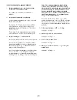
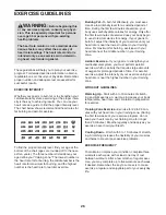
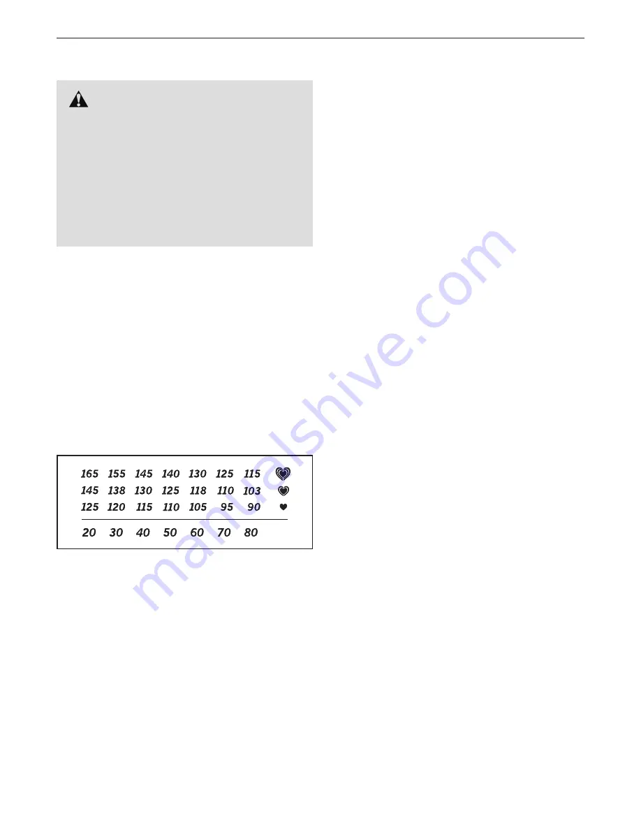
The chart below shows recommended heart rates for 
fat burning and aerobic exercise.

To find the proper intensity level, find your age at the 
bottom of the chart (ages are rounded off to the near-
est ten years). The three numbers listed above your 
age define your ““training zone.”” The lowest number is 
the heart rate for fat burning, the middle number is the 
heart rate for maximum fat burning, and the highest 
number is the heart rate for aerobic exercise.

Burning Fat

——To burn fat effectively, you must exer-

cise at a low intensity level for a sustained period of 
time. During the first few minutes of exercise, your 
body uses carbohydrate calories for energy. Only after 
the first few minutes of exercise does your body begin 
to use stored fat calories for energy. If your goal is to 
burn fat, adjust the intensity of your exercise until your 
heart rate is near the lowest number in your training 
zone. For maximum fat burning, exercise with your 
heart rate near the middle number in your training 
zone.

Aerobic Exercise

——If your goal is to strengthen your 

cardiovascular system, you must perform aerobic 
exercise, which is activity that requires large amounts 
of oxygen for prolonged periods of time. For aerobic 
exercise, adjust the intensity of your exercise until your 
heart rate is near the highest number in your training 
zone. 

WORKOUT GUIDELINES

Warming Up

——Start with 5 to 10 minutes of stretch-

ing and light exercise. A warm-up increases your body 
temperature, heart rate, and circulation in preparation 
for exercise. 

Training Zone Exercise

——Exercise for 20 to 30 min-

utes with your heart rate in your training zone. (During 
the first few weeks of your exercise program, do not 
keep your heart rate in your training zone for longer 
than 20 minutes.) Breathe regularly and deeply as you 
exercise ; never hold your breath. 

Cooling Down

——Finish with 5 to 10 minutes of stretch-

ing. Stretching increases the flexibility of your muscles 
and helps to prevent post-exercise problems.

EXERCISE FREQUENCY

To maintain or improve your condition, complete three 
workouts each week, with at least one day of rest 
between workouts. After a few months of regular exer-
cise, you may complete up to five workouts each week, 
if desired. Remember, the key to success is to make 
exercise a regular and enjoyable part of your everyday 
life.

    WARNING:

 Before beginning this 

or any exercise program, consult your physi-
cian. This is especially important for persons 
over age 35 or persons with pre-existing 
health problems.

The heart rate monitor is not a medical device. 
Various factors may affect the accuracy of 
heart rate readings. The heart rate monitor is 
intended only as an exercise aid in determin-
ing heart rate trends in general.

Summary of Contents for 831.23950.1

Page 1: ...No Write the serial number in the space above for reference www nordictrack com To register your product and activate your warranty today go to www nordictrackservice com registration For service at any time go to www nordictrackservice com Or call 1 800 TO BE FIT 1 800 862 3348 Mon Fri 6 a m 6 p m MT Sat 8 a m 12 p m MT Please do not contact the store ACTIVATE YOUR WARRANTY CUSTOMER CARE ...

Page 2: ...al size TABLE OF CONTENTS WARNING DECAL PLACEMENT NORDICTRACK is a registered trademark of ICON IP Inc WARNING DECAL PLACEMENT 2 IMPORTANT PRECAUTIONS 3 BEFORE YOU BEGIN 6 PART IDENTIFICATION CHART 7 ASSEMBLY 8 THE CHEST HEART RATE MONITOR 12 HOW TO USE THE ELLIPTICAL 13 FCC INFORMATION 23 MAINTENANCE AND TROUBLESHOOTING 24 EXERCISE GUIDELINES 26 PART LIST 28 EXPLODED DRAWING 30 ORDERING REPLACEME...

Page 3: ...ug the power cord into a grounded circuit 10 Do not modify the power cord or use an adapter to connect the power cord to an improper receptacle Keep the power cord away from heated surfaces Do not use an extension cord 11 Do not operate the elliptical if the power cord or plug is damaged or if the elliptical is not working properly 12 DANGER Always unplug the power cord and switch the power switch...

Page 4: ...4 ...

Page 5: ...5 UTS all STANDARD SERVICE PLANS ...

Page 6: ...ur workouts at home more effec tive and enjoyable For your benefit read this manual carefully before you use the elliptical If you have questions after reading this manual please see the front cover of this manual To help us assist you note the product model number and serial number before contacting us The model number and the location of the serial number decal are shown on the front cover of th...

Page 7: ... drawings below to identify the small parts needed for assembly The number in parentheses below each drawing is the key number of the part from the PART LIST near the end of this manual The number following the key number is the quantity needed for assembly Note If a part is not in the hardware kit check to see if it has been preassembled Extra parts may be included ...

Page 8: ...gistration provides the following benefits activates your product manufacturer s warranty saves you time if you ever need to contact Customer Care allows us to notify you of upgrades and offers Note If you do not have Internet access call Customer Care see the front cover of this manual to register your product 1 2 With the help of a second person place some of the packing materials not shown unde...

Page 9: ...ront of the Frame 1 Have the second per son hold the Frame to prevent it from tipping while you complete this step Identify the Right Front Stabilizer 6 and orient it as shown Attach the Right Front Stabilizer 6 to the Frame 1 with three M10 x 20mm Screws 144 start all three Screws and then tighten them Attach the Left Front Stabilizer not shown in the same way Then remove the packing materials fr...

Page 10: ...he Shield Cover 56 downward onto the Rear Shield 75 104 142 56 1 4 8 75 5 Orient the Front Stabilizer Cover 8 as shown and route the Power Cord not shown over the top of the Front Stabilizer Cover Then press the Front Stabilizer Cover onto the Frame 1 Attach the Front Stabilizer Cover 8 with two M4 x 16mm Screws 104 ...

Page 11: ...n it so that it is flush with the Right Upper Body Leg 36 Attach the Left Upper Body Arm 47 in the same way 7 Locate the Right Upper Saddle Bracket 121 on the Right Roller Arm 45 Next locate the Lower Saddle Bracket 26 on the right side of the elliptical Attach the Right Upper Saddle Bracket 121 to the Lower Saddle Bracket 26 with two M10 x 70mm Screws 139 9 Make sure that all parts are properly t...

Page 12: ...atures above 122 F 50 C or below 14 F 10 C Do not excessively bend or stretch the sensor when using or storing the heart rate monitor To clean the sensor use a damp cloth and a small amount of mild soap Then wipe the sensor with a damp cloth and thoroughly dry it with a soft towel Never use alcohol abrasives or chemicals to clean the sensor Hand wash and air dry the chest strap TROUBLESHOOTING If ...

Page 13: ...eptacle outlet box covers are not grounded Before using an adapter contact a quali fied electrician to determine whether the outlet box cover is grounded before using an adapter The temporary adapter should be used only until a properly grounded outlet can be installed by a qualified electrician HOW TO ADJUST THE POSITIONS OF THE PEDALS Each pedal can be adjusted to several positions To adjust eac...

Page 14: ...E ON THE ELLIPTICAL To mount the elliptical hold the upper body arms or the handlebars and step onto the pedal that is in the lower position Then step onto the other pedal Push the pedals until they begin to move with a continuous motion Note The crank arms can turn in either direction It is recommended that you turn the crank arms in the direction shown by the arrow however for variety you can tu...

Page 15: ...nywhere in the world with customizable Google Maps Download training workouts designed to help you reach your personal goals Measure your progress by competing against other users in the iFit community Upload your workout results to the iFit cloud and track your accomplishments Set calorie time or distance goals for your workouts Choose and download sets of weight loss workouts Go to iFit com to l...

Page 16: ...you exercise To use the manual mode see page 17 To use an onboard workout see page 19 To use a set a goal workout see page 20 To use an iFit workout see page 21 To change console set tings see page 22 To use the sound system see page 22 Note If there is a sheet of plastic on the display remove the plastic HOW TO TURN ON THE POWER IMPORTANT If the elliptical has been exposed to cold temperatures al...

Page 17: ...he distance that you have pedaled in miles or kilometers Pulse This display mode will show your heart rate when you use the handgrip heart rate monitor or the included chest heart rate monitor see step 5 Ramp This display mode will show the incline level of the ramp for a few seconds each time the incline level changes Resistance Resist This display mode will show the resistance level of the pedal...

Page 18: ... flash in the display each time your heart beats one or two dashes will appear and then your heart rate will be shown For the most accurate heart rate reading hold the contacts for at least 15 seconds If the display does not show your heart rate make sure that your hands are positioned as described Be careful not to move your hands excessively or to squeeze the contacts tightly For optimal perfor ...

Page 19: ...ash If a different resis tance level ramp incline level and or target rpm is programmed for the next segment the resistance level ramp incline level and or target rpm will appear in the display for a few seconds to alert you The resistance of the pedals and the incline level of the ramp will then change As you exercise you will be prompted to keep your pedaling speed near the target rpm for the cu...

Page 20: ...ually change the resistance level or the ramp incline level during a calorie goal workout the length of the workout will adjust auto matically to ensure that you meet your calorie goal Note The calorie goal is an estimate of the number of calories that you will burn during the workout The actual number of calories that you burn will depend on various factors such as your weight In addition if you ...

Page 21: ... scheduled Press the Track button to re run a recent iFit work out from your schedule Next press the increase and decrease buttons to select the desired work out Then press the Enter button to start the workout For more information about iFit workouts please see www iFit com When you select an iFit workout the display will show the duration of the workout and the approxi mate number of calories yo...

Page 22: ...lected contrast level will appear in the display Press the Power Ramp increase and decrease buttons to adjust the contrast level The following additional settings will be available if an iFit module is inserted into the console Trainer Voice The currently selected setting for the audio coach will appear in the display Press the Enter button repeatedly to turn the audio coach ON or OFF Default Menu...

Page 23: ... equipment does cause harmful interference to radio or television reception which can be determined by turning the equipment off and on try to correct the interference by one or more of the following measures Reorient or relocate the receiving antenna Increase the separation between the equipment and the receiver Connect the equipment into an outlet on a circuit different from that to which the re...

Page 24: ... any excess grease HOW TO CALIBRATE THE RAMP If the ramp is not functioning properly the ramp may need to be calibrated To calibrate the ramp press and hold the Calorie Workouts button for several seconds until the test mode appears in the display Next press the Calorie Workouts button again Then press the Power Ramp increase or decrease button to calibrate the ramp The ramp will move upward and d...

Page 25: ...wdriver and pry off the Shield Cover 56 and slide it upward Then remove the four M4 x 16mm Screws not shown from the upper and lower ends of the Rear Shield 75 and remove the Rear Shield Then look between the Shields 73 74 and locate the M8 Locknut 102 Tighten the Locknut until the Drive Belt 113 is tight When you have properly adjusted the drive belt reat tach the rear shield and press the shield...

Page 26: ...ic Exercise If your goal is to strengthen your cardiovascular system you must perform aerobic exercise which is activity that requires large amounts of oxygen for prolonged periods of time For aerobic exercise adjust the intensity of your exercise until your heart rate is near the highest number in your training zone WORKOUT GUIDELINES Warming Up Start with 5 to 10 minutes of stretch ing and light...

Page 27: ...illes Stretch With one leg in front of the other reach forward and place your hands against a wall Keep your back leg straight and your back foot flat on the floor Bend your front leg lean forward and move your hips toward the wall Hold for 15 counts then relax Repeat 3 times for each leg To cause further stretching of the achilles tendons bend your back leg as well Stretches Calves achilles tendo...

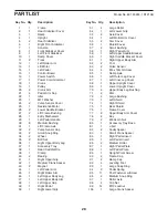
Page 28: ...al 50 1 Right Lower Grip 51 4 Large Roller 52 1 Left Lower Grip 53 2 Axle Cover 54 1 Left Roller Arm Cover 55 2 Disc Cover 56 1 Shield Cover 57 4 Small Bushing 58 1 Right Pedal Arm 59 1 Left Upper Saddle Bracket 60 1 Right Saddle Bracket Cover 61 1 Right Upper Body Arm 62 2 Foot 63 2 Pulse Sensor 64 4 M4 x 19mm Screw 65 1 Ramp Axle 66 1 Left Outer Leg Cover 67 1 Left Inner Leg Cover 68 1 Upper Upr...

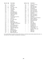
Page 29: ...Bolt 131 2 M8 Flat Head Screw 132 8 M10 x 20mm Screw 133 4 M6 Washer 134 1 M10 x 48mm Bolt 135 1 M10 x 36mm Bolt 136 4 M10 Washer 137 16 M4 x 10mm Screw 138 10 M6 x 12mm Screw 139 4 M10 x 70mm Screw 140 2 M10 x 60mm Screw 141 4 M4 Washer 142 2 M10 x 75mm Screw 143 4 M10 x 45mm Bolt 144 12 M10 x 20mm Screw 145 2 M8 Washer 146 4 M4 x 12mm Flat Head Screw 147 1 M8 Small Washer 148 4 M2 6 x 33mm Screw...

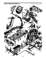
Page 30: ...9 63 66 68 65 62 11 67 69 72 76 73 75 77 80 88 85 89 90 92 92 91 95 95 95 97 105 106 107 129 136 136 132 132 104 99 132 144 122 99 140 135 144 144 104 104 129 132 104 104 104 104 104 142 116 104 104 104 146 104 104 137 137 104 104 104 148 104 127 3 134 10 123 EXPLODED DRAWING A Model No 831 23950 1 R1213B ...

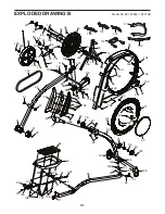
Page 31: ...96 98 98 93 95 95 100 103 129 99 99 117 139 104 101 147 102 102 145 145 141 132 136 104 104 128 131 117 118 130 130 108 112 114 115 109 104 104 149 149 149 149 104 132 138 137 138 102 102 110 111 113 30 30 41 50 53 61 125 150 151 152 152 126 70 70 77 104 120 119 143 99 104 104 64 124 95 EXPLODED DRAWING B Model No 831 23950 1 R1213B ...

Page 32: ...le for a minimal trip charge This warranty does not extend to freight damage to the product This warranty will automatically be voided if the product is used as a store display model if the product is purchased or transported outside the USA if all instructions in this manual are not followed if the product is abused or improperly or abnormally used or if the product is used for commercial or rent...

Reviews: