background image

7

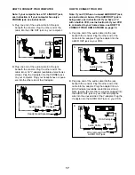
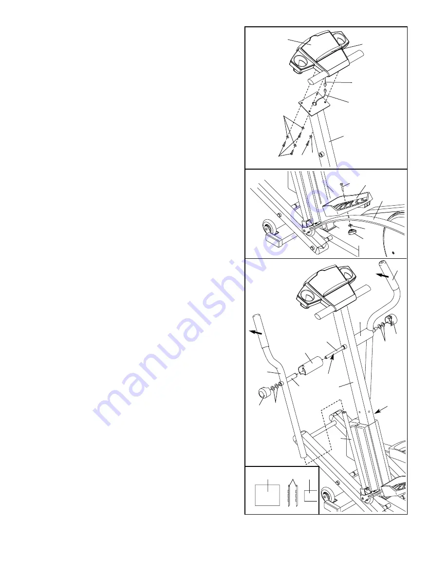
6. Connect the wire harness on the Console (87) to the

Extension Wire Harness (51). 

Attach the Console (87) to the Upright (2) with the four
Console Screws (35) and the four Console Washers
(93) packaged with the Console. 

Be careful to avoid

pinching the wire harnesses.

Snap the bookrack onto the Console (87) in the location
shown.

6

87

Wire

Harness

Bookrack

35

93

93

35

51

2

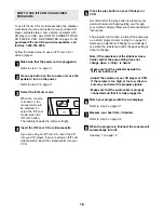
7. Identify the Left Pedal (41). Attach the Left Pedal to the

Left Spring Arm (3) with an M10 x 33mm Carriage Bolt
(61), an M10 Washer (63), and an Adjustment Knob
(77) as shown. Note: The Left Pedal can be attached in
any of five positions (see HOW TO ADJUST THE PED-
ALS on page 9).

Attach the Right Pedal (not shown) in the same way.
Make sure that both Pedals are in the same position.

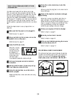
8. Apply a small amount of the included Teflon

®

lubricant

to a paper towel. Rub a thin film of the lubricant onto
the Chrome Tubes (21). Next, slide the Left Upper
Body Arm (7), which is marked with a sticker, onto the
left Chrome Tube. Slide the Right Upper Body Arm (75)
onto the right Chrome Tube. 

Make sure that the

Upper Body Arms are on the correct sides—the
upper ends should bend in the direction shown by
the arrows. 

Next, slide an Axle Cover (74) onto the

post on each Upper Body Arm.

Apply grease to the Arm Axle (19). Insert the Arm Axle
into the right Axle Cover (74) and the Right Upper Body
Arm (75). Next, insert the Arm Axle into the Upright (2)
until the left end of the Arm Axle is flush with the left
side of the Upright. Then, insert the Arm Axle into the
left Axle Cover (74) and the Left Upper Body Arm (7).  

Center the Arm Axle (19). Using the included pedal
tool, tap two Push Nuts (15) 

about 1/8”

onto each end

of the Arm Axle. Make sure that the Push Nuts are
turned as shown in the inset drawing. (Note: It may be
helpful if another person holds a block of wood against
one end of the Arm Axle while you tap Push Nuts onto
the other end.) Then, press an Axle Cap (34) onto each
end of the Arm Axle.

8

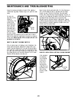
9.

Make sure that all parts of the elliptical crosstrainer are properly tightened.

Note: Some hardware may

be left over after assembly is completed. 

21

21

2

74

Post

Grease

74

19

34

34

15

15

7

75

Pedal Tool 15

19

41

63

3

61

77

7

Summary of Contents for 831.298650

Page 1: ...arts we will guar antee complete satisfaction through direct assistance from our factory TO AVOID UNNECESSARY DELAYS PLEASE CALL DIRECT TO OUR TOLL FREE CUSTOMER HOT LINE The trained techni cians on o...

Page 2: ...3 BEFORE YOU BEGIN 4 ASSEMBLY 5 HOW TO USE THE ELLIPTICAL CROSSTRAINER 8 MAINTENANCE AND TROUBLESHOOTING 20 CONDITIONING GUIDELINES 21 PART LIST 22 EXPLODED DRAWING 23 HOW TO ORDER REPLACEMENT PARTS B...

Page 3: ...unting dismounting or using the elliptical crosstrainer 10 Keep your back straight when using the ellip tical crosstrainer do not arch your back 11 If you feel pain or dizziness while exercis ing stop...

Page 4: ...addi tional questions please call our Customer Service Department toll free at 1 888 825 2588 Monday through Friday 6 a m until 6 p m Mountain Time excluding holidays To help us assist you please note...

Page 5: ...ngs below to identify the small parts used in assembly The number in parenthesis below each drawing refers to the key number of the part from the PART LIST on page 22 The second number refers to the q...

Page 6: ...er 33 onto an M8 x 19mm Screw 30 Tighten the Screw into one end of the other Incline Axle 29 Next apply a small amount of grease to the Incline Axle Raise the Incline Ramp 5 Insert the Incline Axle 29...

Page 7: ...Right Upper Body Arm 75 onto the right Chrome Tube Make sure that the Upper Body Arms are on the correct sides the upper ends should bend in the direction shown by the arrows Next slide an Axle Cover...

Page 8: ...pulse sensor may be discarded A 87 Screws 1 B C D Cylinder 2 87 HOW TO PLUG IN THE POWER CORD This product must be grounded If it should malfunction or break down grounding provides a path of least re...

Page 9: ...sure that both pedals are in the same position EXERCISING ON THE ELLIPTICAL CROSSTRAINER To mount the elliptical crosstrainer hold the handgrip pulse sensor and step onto the pedal that is in the low...

Page 10: ...y IFIT com technology is like having a per sonal trainer right in your home Using the included audio cable you can connect the elliptical crosstrainer to your home stereo portable stereo or computer a...

Page 11: ...Resistance buttons are pressed it will take a moment for the pedals to reach the selected resistance level To vary the affect of your exercise on the elliptical crosstrainer increase or decrease the a...

Page 12: ...sor see page 19 and hold the handgrip pulse sensor at the same time the console may not display your heart rate accurately If there are thin sheets of plastic on the metal contacts on the hand grip pu...

Page 13: ...esis tance settings will move one column to the left The resistance setting for the second segment will then be shown in the flashing Current Segment column and the resistance of the ellipti cal cross...

Page 14: ...Age button and go to step 5 If you have not entered your age press the or button repeatedly these are the buttons that select resistance levels 9 and 10 to enter your age and then press the Enter Age...

Page 15: ...r when the next seg ment begins the resistance will automatically adjust to the setting for the next segment If you stop exercising for six seconds or longer a tone will sound and the program will pau...

Page 16: ...nes into the other side of the Y adapter HOW TO CONNECT YOUR HOME STEREO Note If your stereo has an unused LINE OUT jack see instruction A below If the LINE OUT jack is being used see instruction B A...

Page 17: ...built in VCR see instruction B If your VCR is connected to your home stereo see HOW TO CONNECT YOUR HOME STEREO on page 16 A Plug one end of the audio cable into the jack beneath the console Plug the...

Page 18: ...to your VCR Press the play button on your CD player or VCR A moment after the play button is pressed your personal trainer will begin guiding you through your workout Simply follow your personal train...

Page 19: ...tart your Web browser if necessary and go to our Web site at www iFIT com Follow the desired links on our Web site to select a program Read and follow the on line instructions for using a program Foll...

Page 20: ...from both Side Shields and Pedal Disks Pull the Pedal Disks out of the Side Shields Lift the Side Shields off the elliptical crosstrainer Next locate the Reed Switch 50 Turn the Flywheel 37 until the...

Page 21: ...to strengthen your cardiovascular sys tem your exercise must be aerobic Aerobic exer cise is activity that requires large amounts of oxygen for prolonged periods of time This increases the demand on...

Page 22: ...n Wire Harness 52 1 Reed Switch Bracket 53 2 Spring Bracket 54 1 Reed Switch Clamp 55 1 Magnet 56 1 Left Rear Spring Bracket 57 1 Right Rear Spring Bracket 58 4 M8 Split Washer 59 1 Rear Stabilizer 60...

Page 23: ...31 31 82 81 7 49 20 21 74 23 23 74 19 49 23 15 23 34 48 88 71 73 73 72 72 2 20 44 35 93 25 60 60 43 43 27 27 53 56 63 61 77 78 79 92 86 92 86 92 92 22 67 73 14 73 21 46 45 62 90 62 46 45 46 65 46 22...

Page 24: ...or if necessary the entire product for repair USER S MANUAL It is VERY IMPORTANT THAT YOU READ THE MANUAL before operating the Product Remember to do the periodic maintenance requirements specified in...

Reviews: