background image

15

HOW TO USE THE RANDOM PROGRAM

The RANDOM program will automatically change the

resistance of the pedals during your workout. Each

time the program is selected, the resistance settings of

the program will be different.

Plug in the power cord or begin pedalling to

activate the console.

See HOW TO ACTIVATE THE CONSOLE on

page 10.

Select the RANDOM program.

To select the RANDOM program, press the RAN-

DOM button. The indicator on the button will light,

and the word “RANDOM” will appear in the main

display for a moment. Note: To select a different

RANDOM program, simply press the RANDOM

button again.

Enter your age.

See step 3 on page 14.

Enter your weight.

See step 4 on page 14.

Enter a program time.

See step 5 on page 14.

Enter a maximum resistance setting.

Next, the words “MAX RESIST” and the maximum

resistance setting of the program will appear in

the main display. If you wish to change the maxi-

mum resistance setting, press the + and – buttons

beside the ENTER button. (Note: If the maximum

resistance setting is increased, the intensity level

of the program will be increased.) When the de-

sired maximum resistance setting is shown, press

the ENTER button.

Begin exercising.

The program is divided into 30-second segments.

One resistance setting is programmed for each

segment. Note: The same resistance setting may

be programmed for two or more consecutive seg-

ments.

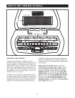
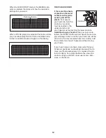
During the pro-

gram, the matrix

will show your

progress and the

resistance settings

of the program.

During the first 30-

second segment of

the program, the

left column of the matrix will flash. During the last

four seconds of the first segment, the column to

the right will also flash. If the resistance of the ped-

als is about to change, a series of tones will sound

and the resistance setting will flash in the main dis-

play. When the first segment ends, the column to

the right will continue to flash, and the resistance

of the pedals will automatically change if a differ-

ent resistance setting is programmed for the next

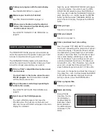
segment. Note: If all of the indicators in the flash-

ing column are lit,

the indicators in all columns

may shift downward

temporarily.

At the end of each segment, a tone will sound, the

next column to the right will begin to flash, and the

resistance of the pedals will automatically change

if a different resistance setting is programmed for

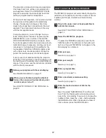
the next segment. When you have completed the

first 8 minutes of the program, the same column

will continue to flash, and

all columns of indicators

will shift one position to the left.

The columns of in-

dicators will continue to shift to the left at the end

of each segment, until the last segment of the pro-

gram is shown in the far right column of the matrix.

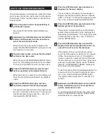
The next column to the right will then begin to flash

at the end of each segment,

until the program is

completed.

During the program, you can change the resis-

tance of the pedals, if desired, by pressing the

RESI and – buttons or the QUICK-

TOUCH RESISTANCE buttons. However, when

the current segment ends, the resistance will au-

tomatically change if a different resistance setting

is programmed for the next segment. Note: The

program ends with a two-minute cool-down period.

During this period, the resistance level cannot be

changed.

6

5

4

3

7

1

2

Flashing Column

Summary of Contents for 9600 Elliptical Trainer

Page 1: ...ce Model No CEL42541 Model No CEL45041 Serial No The serial number is found in the location shown below Write the serial number in the space above QUESTIONS At FreeMotion Fitness we re committed to pr...

Page 2: ...Trainer 5 How to Set Up the Elliptical Trainer 7 How to Upgrade the Console 8 SECTION 2 How to Use the Basic Console 9 SECTION 3 Maintenance and Troubleshooting 21 SECTION 4 Exercise Guidelines 23 SE...

Page 3: ...OF THE PRODUCT NordicTrack 9600E elliptical trainer The SERIAL NUMBER OF THE PRODUCT see the front cover of this manual for the location When ordering replacement parts please also give the KEY NUMBE...

Page 4: ...tor to connect the power cord to an improper receptical see HOW TO CONNECT THE POWER CORD on page 7 Keep the power cord away from heated surfaces Do not use an extension cord 11 Keep your back straig...

Page 5: ...this manual To help us assist you please note your product model number and serial number before calling The model num ber of your elliptical trainer is CEL42541 or CEL45041 The serial number can be...

Page 6: ...Washers 100 Repeat this step for the Right Handlebar Arm not shown 2 Have another person hold the Upright 2 in the po sition shown Connect the Lower Power Wire 96 to the Upper Power Wire 97 Connect t...

Page 7: ...6 3 Attach the Upright Cover 29 to the Upright 2 with three 8 x 1 2 Button Head Screws 92 Attach the Water Bottle Holder 26 to the Frame 1 with four 8 x 1 2 Button Head Screws 92 3 29 92 1 2 26 92...

Page 8: ...he el liptical trainer has a Workout TV console a power cord must be used for the TV to be operated A power cord is included with the Workout TV console To use a power cord first plug one end of the p...

Page 9: ...Basic console see page 9 To learn about the features of the Workout TV console see the user s manual included with the Workout TV console To upgrade your console and expand the capabilities of your el...

Page 10: ...fective workout The console also offers two PULSE programs that automatically adjust the resistance of the pedals to keep your heart rate near a target level during your workouts Note The PULSE progra...

Page 11: ...RN OFF THE CONSOLE If the power cord is not being used and if the ped als are not moved for a short period of time the con sole will automatically turn off If the power cord is being used and if the p...

Page 12: ...i mated maximum heart rate The display will change from one number to the other every few seconds Speed RPM The right end of the main display will show your pedalling speed in miles per hour or kilome...

Page 13: ...t be resting on the upper contacts and your fingers must be touching the lower contacts Avoid moving your hands When your pulse is de tected the HEART RATE indicator above the main dis play will begin...

Page 14: ...elect a resis tance setting higher than 8 the indicators in all columns will shift downward until you select a lower resistance setting After every 30 seconds that you exercise a tone will sound and t...

Page 15: ...lumn of the ma trix will flash During the last four seconds of the first segment the column to the right will also flash When the first segment ends a tone will sound and the column to the right will...

Page 16: ...mn of the matrix will flash During the last four seconds of the first segment the column to the right will also flash If the resistance of the ped als is about to change a series of tones will sound a...

Page 17: ...t Next the words CONSTANT MODE will appear in the main display If you plan to use the CON STANT PULSE program press the ENTER but ton If you plan to use the VARIABLE PULSE pro gram press the or button...

Page 18: ...curs see the instructions included with the chest pulse sensor Follow your progress with the main display See THE MAIN DISPLAY on page 11 When you are finished using the elliptical trainer the console...

Page 19: ...tivate the console See HOW TO ACTIVATE THE CONSOLE on page 10 Select the PLATEAU program To select the PLATEAU program press the PLATEAU button The indicator on the button will light and the word PLAT...

Page 20: ...ee HOW TO ACTIVATE THE CONSOLE on page 10 Select the desired program Press the FOOTHILLS PEAKS or ALL TERRAIN button The indicator on the button will light and the word FOOTHILLS PEAKS or ALL TER RAIN...

Page 21: ...uage for the main display The main display can display text messages in English International English German Spanish Italian or French To change the language press the and buttons beside the ENTER but...

Page 22: ...ole can display data using the English system miles and pounds or the metric system kilometres and kilograms To change the system of measurement see step 7 on page 20 3 SYMPTOM THE PULSE SENSOR DOES N...

Page 23: ...Generator Tension Bolt 103 1 4 turn until the Drive Belt 15 stops slipping Retighten the four 1 4 x 3 8 Cap Screws and se cure the Left Side Shield with the nine 1 4 x 3 4 Button Head Screws 59 Secure...

Page 24: ...l training aerobic or cardiovascular level the Fitness level Advanced trainer or those wish ing to do sports athletic conditioning or interval training workouts should exercise at 80 to 85 per cent of...

Page 25: ...ns bend your back leg as well Stretches Calves achilles tendons and ankles 3 Hamstring Stretch Sit with one leg extended Bring the sole of the opposite foot toward you and rest it against the inner th...

Page 26: ...e full 20 minutes from the start which is common try to exercise for five minutes at a time a couple of times a day Recent research indicates that several short workouts in one day can also provide fi...

Page 27: ...robic condition ing It consists of spurts of high intensity activity fol lowed by active rest periods of exercise at a lower in tensity For example a one minute spurt of high resis tance fast exercise...

Page 28: ...rew 48 8 3 8 x 1 1 4 Button Head Screw 49 4 1 4 x 3 8 Cap Screw 50 2 1 2 x 2 Button Head Screw 51 2 4 Nylon Locknut 52 4 8 x 3 4 Screw 53 4 8 x 1 4 Nylon Screw 54 14 10 x 3 8 Pedal Screw 55 4 3 8 x 5...

Page 29: ...T CUSTOMER CARE on page 2 of this manual 95 1 Battery Pack 96 1 Lower Power Wire 97 1 Upper Power Wire 98 1 Power Input Wire 99 2 3 8 x 3 4 Shoulder Screw 100 4 3 8 Lock Washer 101 1 Upper CATV Cable...

Page 30: ...3 34 69 35 29 30 49 1 92 92 50 46 46 31 70 70 46 31 46 50 36 36 25 53 32 71 59 37 37 59 59 37 15 75 82 81 80 79 78 77 76 74 42 42 91 90 47 86 86 86 85 85 87 87 88 57 51 98 96 97 95 102 101 103 EXPLODE...

Page 31: ...30 59 5 59 59 59 59 7 64 73 6 9 63 63 8 3 9 4 62 62 59 59 59 59 5 59 58 52 52 52 52 EXPLODED DRAWING Model Nos CEL42541 CEL45041 Part 2 of 3 R1004A...

Page 32: ...42 45 41 56 39 23 40 72 43 24 99 21 13 11 24 66 94 66 94 84 10 12 104 104 59 68 38 65 44 42 66 45 41 56 83 94 61 60 93 93 28 104 22 55 55 14 67 67 54 54 67 104 42 100 100 48 100 100 43 EXPLODED DRAWIN...

Page 33: ...32 Part No XXXXXX R1004A Printed in USA 2004 ICON IP Inc FreeMotion Fitness Inc 1096 Elkton Suite 600 Colorado Springs CO 80907...

Reviews: