background image

GETTING STARTED

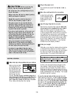
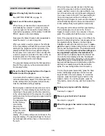
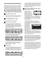
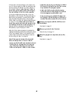
Attach the clip to the waistband of your clothes.

Stand on the foot rails
of the treadmill. Find
the clip attached to the
key and slide the clip
onto the waistband of
your clothes. Next, in-
sert the key into the
console. Test the clip by carefully taking a few
steps backward until the key is pulled from the
console. If the key is not pulled from the con-
sole, adjust the position of the clip as needed.
Then, remove the key from the console.

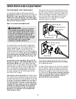
Plug in the power cord.

See HOW TO PLUG IN THE POWER CORD on
page 8. 

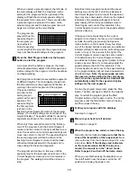
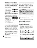
Move the on/off switch to the on position.

Locate the on/off switch
on the treadmill near the
power cord. Move the
on/off switch to the on
position. 

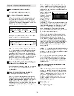
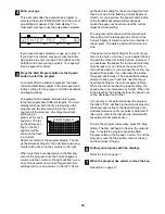
Insert the key fully into the console.

Stand on the foot rails of the treadmill. Attach the
clip securely to the waistband of your clothes.
Next, insert the key into the console. After a 
moment, various displays and indicators on the
console will light. Note: When the key is inserted,
the treadmill incline system may automatically 
calibrate itself—the treadmill will rise to the highest
incline level and then return to the lowest incline
level. During calibration, the left side of the main
display will show two dashes (– –) and the time 
indicator below the display will flash. 

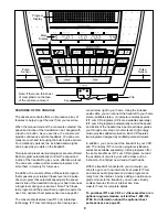
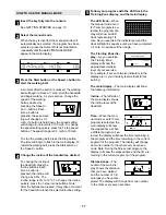
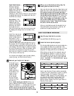
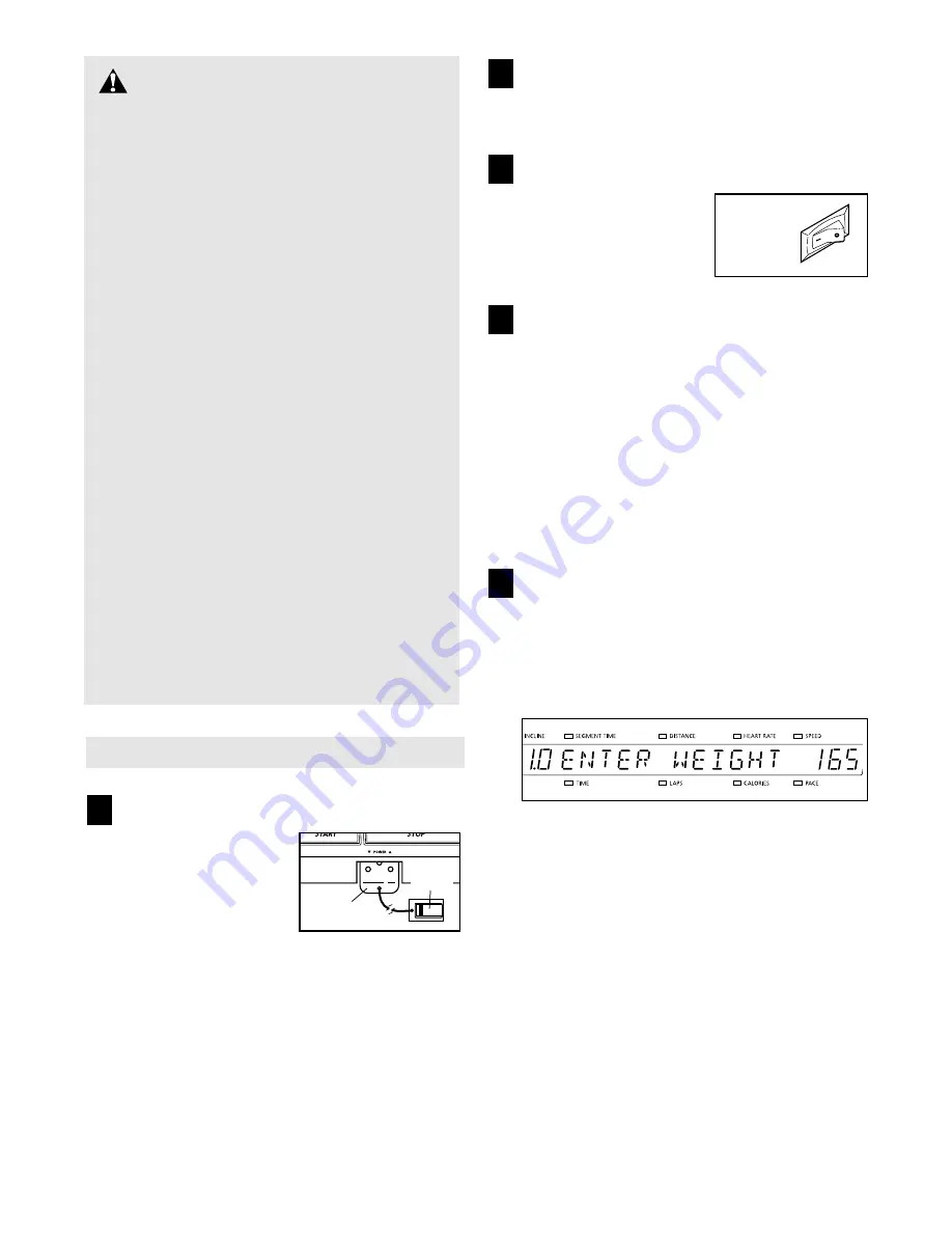
Enter your weight.

Although you can use the console without entering
your weight, the console will count the calories
you burn more accurately if you enter your weight.
To enter your weight, press either of the Enter
Weight buttons. The words “ENTER WEIGHT”

and the current weight setting will appear in the
main display. Press the Enter Weight buttons
again to enter your weight. The buttons can be
held down to enter your weight quickly. Four sec-
onds after the buttons are last pressed, the weight
setting will disappear from the display. Your weight
will then be saved in memory. 

To use the manual mode of the console, follow the
steps beginning on page 11. To use a preset program,
see page 12. To create and use a custom program,
see pages 14 and 15. To use the fitness test program,
see page 16. To use the pulse-driven program, see
page 17. To use an iFIT.com CD or video program,
refer to page 21. To use an iFIT.com program di-
rectly from our internet site
, see page 23.

5

4

3

2

1

CAUTION:

Before operating the 

console, read the following precautions.

• Do not stand on the walking belt when turn-

ing on the power. 

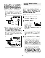
• Always wear the clip (see the drawing below)

while operating the treadmill. 

• Adjust the speed in small increments in

order to avoid sudden jumps in speed.

• The pulse sensor is not a medical device.

Various factors may affect the accuracy of
heart rate readings. The pulse sensor is in-
tended only as an exercise aid in determin-
ing heart rate trends in general.

• If you have heart problems, or if you are over

60 years of age and have been inactive, do
not use the pulse-driven program. If you are
taking medication regularly, consult your
physician to find whether the medication will
affect your exercise hart rate.

• Using hand weights and not holding the

handrails may compromise your ability to
maintain your balance. Hand weights should
be used only by experienced users.

• To reduce the possibility of electric shock,

keep the console dry. Avoid spilling liquids
on the console and place only a sealed water
bottle in the water bottle holder.

On

Position

Clip

10

Key

Summary of Contents for Apex 5100

Page 1: ...om new products prizes fitness tips and much more QUESTIONS As a manufacturer we are com mitted to providing complete customer satisfaction If you have questions or if there are missing parts we will...

Page 2: ...ASSEMBLY 6 OPERATION AND ADJUSTMENT 8 HOW TO FOLD AND MOVE THE TREADMILL 25 TROUBLE SHOOTING 26 CONDITIONING GUIDELINES 28 PART LIST 30 ORDERING REPLACEMENT PARTS 31 LIMITED WARRANTY Back Cover Note A...

Page 3: ...si pation of 450 joules The surge suppressor must be electrically rated for 120 volts AC and 15 amps To purchase a surge suppressor see your local NordicTrack dealer or call 1 888 825 2588 and order p...

Page 4: ...R Always unplug the power cord immediately after use before cleaning the treadmill and before performing the main tenance and adjustment procedures de scribed in this manual Never remove the motor hoo...

Page 5: ...25 2588 Monday through Friday 6 a m until 6 p m Mountain Time ex cluding holidays To help us assist you please note the product model number and serial number before calling The model number of the tr...

Page 6: ...7 114 2 3 Place one of the Handrail Spacers 92 on the right Upright 83 as shown with the cutout on the indicated side see inset drawing A Pull the Upright Wire Harness 131 up through the cutout Place...

Page 7: ...ight Upright 83 Turn the Handrail Bushings so they fit against the Upright as shown in the inset drawing Insert two Handrail Bolts 96 with Handrail Washers 95 into the Handrail Bushings 94 the right U...

Page 8: ...grounding plug Plug the power cord into a surge suppressor and plug the surge suppressor into an appropriate outlet that is properly installed and grounded in accordance with all local codes and ordin...

Page 9: ...r right in your home Using the included audio cable you can connect the treadmill to your home stereo portable stereo or computer and play special iFIT com CD programs CD s are available separately iF...

Page 10: ...isplay Press the Enter Weight buttons again to enter your weight The buttons can be held down to enter your weight quickly Four sec onds after the buttons are last pressed the weight setting will disa...

Page 11: ...ressed it may take a moment for the treadmill to reach the selected incline setting Follow your progress with the LED track the Training Zone display and the main display The LED track When the manual...

Page 12: ...hown For the most accurate heart rate reading con tinue to hold the contacts for about 15 seconds When you are finished exercising stop the walking belt and remove the key Step onto the foot rails pre...

Page 13: ...s and the speed settings move to the left if all of the indicators in the Current Segment column are lit the speed set tings may move downward so that only the highest indicators in the columns will a...

Page 14: ...mmed for each segment The speed setting for the first segment will be shown in the flashing Current Segment column of the program dis play The incline settings are not shown in the pro gram display To...

Page 15: ...olumns to the right When only three seconds remain in the first seg ment of the program both the Current Segment column and the column to the right will flash a se ries of tones will sound and all spe...

Page 16: ...tons can be held down to enter your age quickly Your age will then be saved in memory Press the Start Program button or the Speed button to start the program When the button is pressed the main dis pl...

Page 17: ...d the main display will show a fitness level of 0 FL 0 The fitness test program cannot be stopped tem porarily and then restarted However the program can be stopped at any time by pressing the Stop bu...

Page 18: ...lumn As you exercise the speed and or incline of the treadmill will automatically change as needed to keep your heart rate near the current target heart rate setting The program will continue until th...

Page 19: ...le at electronics stores Plug the Y adapter into the PHONES jack on your CD player Plug your headphones into the other side of the Y adapter HOW TO CONNECT YOUR PORTABLE STEREO Note If your stereo has...

Page 20: ...Y adapter Plug the RCA Y adapter into the LINE OUT jack on your stereo HOW TO CONNECT YOUR COMPUTER Note If your computer has a 3 5mm LINE OUT jack see instruction A If your computer has only a PHONE...

Page 21: ...800 735 0768 Follow the steps below to use an iFIT com CD or video program Insert the key fully into the console See GETTING STARTED on page 10 Select the iFIT com mode When the key is in serted the...

Page 22: ...ill begin to flash in the main display Note To use another CD or video program press the Stop button or remove the key and go to step 1 on page 21 Note If the speed or incline of the treadmill does no...

Page 23: ...and on the foot rails Find the clip attached to the key and slide the key onto the waistband of your clothing When the on screen countdown ends the program will begin and the walking belt will begin t...

Page 24: ...ears in the display the console is in the demo mode This mode is intended to be used only when a treadmill is displayed in a store When the console is in the demo mode the power cord can be plugged in...

Page 25: ...l in the stor age position in temperatures above 85 Fahrenheit HOW TO MOVE THE TREADMILL Before moving the treadmill convert the treadmill to the stor age position as described above Make sure that th...

Page 26: ...wait for five minutes and then press the switch back in d Check the on off switch located on the treadmill near the power cord The switch must be in the on position PROBLEM The power turns off during...

Page 27: ...belt is centered b If the walking belt has shifted to the right first remove the key and UNPLUG THE POWER CORD Using the allen wrench turn the left rear roller adjustment bolt coun terclockwise and t...

Page 28: ...goal is to strengthen your cardiovascular sys tem your exercise must be aerobic Aerobic exercise is activity that requires large amounts of oxygen for prolonged periods of time This increases the dem...

Page 29: ...s Stretch With one leg in front of the other reach forward and place your hands against a wall Keep your back leg straight and your back foot flat on the floor Bend your front leg lean forward and mov...

Page 30: ...Lift Motor Bracket 43 1 Lift Motor 44 1 Lift Motor Bolt Bottom 45 4 Isolator 46 1 Electronics Bracket 47 1 Controller 48 12 Belly Pan Screw 49 4 Belly Pan Screw Long 50 1 Belly Pan 51 2 Pinch Decal 52...

Page 31: ...reen Wire M Ring 1 12 Wire Harness 1 User s Manual Includes all parts shown in the box These parts are optional For information about the iFIT com module iFIT com CD s or iFIT com video cassettes call...

Page 32: ...19 1 127 69 56 69 69 8 24 25 15 14 34 34 48 3 43 40 44 101 69 69 69 69 31 31 19 62 64 45 69 69 20 18 109 21 69 65 69 69 100 61 60 57 59 58 128 129 3 3 3 129 130 48 16 45 132 76 16 45 76 132 134 133 10...

Page 33: ...81 73 74 75 75 69 69 86 74 118 118 119 119 117 117 117 117 120 94 95 96 95 94 94 93 93 92 92 80 82 74 74 77 77 96 111 111 108 109 108 109 108 114 114 114 115 113 109 109 109 116 98 99 125 83 84 108 10...

Page 34: ...entire product for repair USER S MANUAL It is VERY IMPORTANT THAT YOU READ THE MANUAL before operating the Product Remember to do the periodic maintenance requirements specified in the Manual to assu...

Reviews: