11
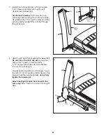
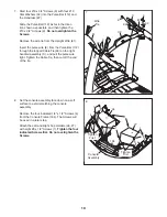
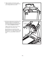
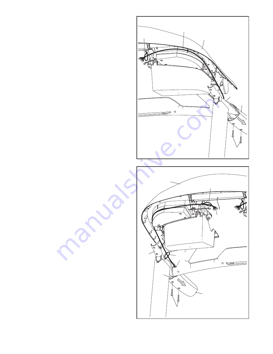
9. Remove the two #8 x 1 1/4" Screws (107) and
slide the Left Handrail Cover (79) back about
1 in. The Screws will be reattached in a later
step. Note: It is not necessary to move the Left
Handrail Insert (84).
With the help of a second person, hold the con-
sole assembly near the left handrail assembly
(B).
Route the Upright Wire (81) around the back of
the console assembly as shown, and insert the
end of the Upright Wire through the indicated
looped Cable Tie (99).
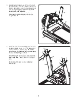
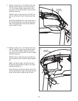
10. Remove the two #8 x 1 1/4" Screws (107) and
slide the Right Handrail Cover (80) back about
1 in. The Screws will be reattached in a later
step. Note: It is not necessary to move the Right
Handrail Insert (85).
With the help of a second person, hold the con-
sole assembly near the right handrail assembly
(C).
Make sure that the pulse wire (E) is inserted
through the looped Cable Tie (99) on the right
handrail assembly (C).
Route the pulse wire (E) around the back of the
console assembly as shown, and insert the end
of the wire through the other Cable Tie (99).
Console
Assembly
Console
Assembly
79
107
107
80
81
99
99
E
9
10
B
C
84
85
99


