13
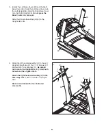
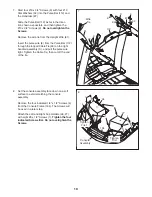
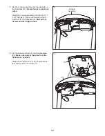
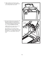
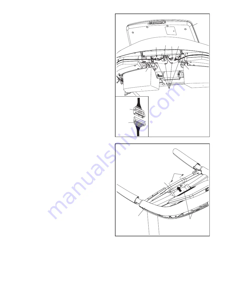
14. Insert the Console Base Back (93) into the hole
in the console assembly and onto the top of the
indicated bracket. Be careful not to pinch any
wires.
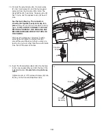
Tighten two #8 x 1/2" Flat Head Screws (31) into
the tray on the Console Base Back (93).
14
Console
Assembly
93
Bracket
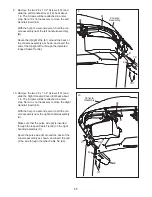
13. Connect the ground wires (G), the 8-pin wires
(F), the 10-pin wires (E), and the four speaker
wires (H) from the Console (103). Note: The
Upright Wire (81) has 8 pins, the pulse wire (E)
has 10 pins, and the speaker wires (H) have 2
pins.
See the inset drawing. The connectors
should slide together easily and snap into
place. If they do not, turn one connector and try
again. IF YOU DO NOT CONNECT THE CON-
NECTORS PROPERLY, THE CONSOLE MAY
BECOME DAMAGED WHEN YOU TURN ON
THE POWER.
After all of the wires are connected, pull the
wires tight and tighten the Cable Ties (99)
around the wires. Make sure that no wires are
resting on any posts other than those with Cable
Ties. Cut off the ends of the ties.
H
G
13
103
E
81
81
99
99
Console
Wire
31
F


