background image

Part No. 321815 R1211B 

Printed in USA © 2011 ICON IP, Inc.

To order replacement parts, please see the front cover of this manual. To help us assist you, be prepared to  

provide the following information when contacting us:

•  the model number and serial number of the product (see the front cover of this manual)

•  the name of the product (see the front cover of this manual)

•   the key number and description of the replacement part(s) (see the PART LIST and the EXPLODED DRAWING 

near the end of this manual)

ICON Health & Fitness, Inc. (ICON) warrants this product to be free from defects in workmanship and 

material, under normal use and service conditions. The frame, drive motor, and walking platform are war-

ranted for a lifetime. Parts and electronics are warranted for five (5) years from the date of purchase. Labor 

is warranted for two (2) years from the date of purchase.

This warranty extends only to the original purchaser (customer). ICON’s obligation under this warranty is 

limited to repairing or replacing, at ICON’s option, the product through one of its authorized service centers. 

All repairs for which warranty claims are made must be preauthorized by ICON. If the product is shipped 

to a service center, freight charges to and from the service center will be the customer’s responsibility. If 

replacement parts are shipped while the product is under warranty, the customer will be responsible for a 

minimal handling charge. For in-home service, the customer will be responsible for a minimal trip charge. 

This warranty does not extend to freight damage to the product. This warranty will automatically be voided 

if the product is used as a store display model, if the product is purchased or transported outside the USA, 

if all instructions in this manual are not followed, if the product is abused or improperly or abnormally used, 

or if the product is used for commercial or rental purposes. No other warranty beyond that specifically set 

forth above is authorized by ICON.

ICON is not responsible or liable for indirect, special, or consequential damages arising out of or in con-

nection with the use or performance of the product; damages with respect to any economic loss, loss of 

property, loss of revenues or profits, loss of enjoyment or use, or costs of removal or installation; or other 

consequential damages of any kind. Some states do not allow the exclusion or limitation of incidental or 

consequential damages. Accordingly, the above limitation may not apply to the customer.

The warranty extended hereunder is in lieu of any and all other warranties, and any implied warranties of 

merchantability or fitness for a particular purpose are limited in their scope and duration to the terms set 

forth herein. Some states do not allow limitations on how long an implied warranty lasts. Accordingly, the 

above limitation may not apply to the customer.

This warranty provides specific legal rights; the customer may have other rights that vary from state to state.

ICON Health & Fitness, Inc., 1500 S. 1000 W., Logan, UT 84321-9813

LIMITED WARRANTY

 IMPORTANT: You must register this product within 30 days of the purchase date to avoid added 

fees for service needed under warranty. Go to www.nordictrackservice.com/registration.

ORDERING REPLACEMENT PARTS

Summary of Contents for C 1500 Pro

Page 1: ...re reference QUESTIONS If you have questions or if parts are damaged or missing DO NOT CONTACT THE STORE please contact Customer Care IMPORTANT Please register this product see the limited warranty on...

Page 2: ...RDERING REPLACEMENT PARTS Back Cover LIMITED WARRANTY Back Cover NORDICTRACK is a registered trademark of ICON IP Inc This drawing shows the locations of the warning decals If a decal is missing or il...

Page 3: ...ll phone chargers into the surge suppressor or into an outlet on the same circuit 12 Use only a surge suppressor that meets all of the specifications described on page 17 To purchase a surge suppresso...

Page 4: ...23 Never insert any object into any opening on the treadmill 24 Inspect and properly tighten all parts of the treadmill regularly 25 DANGER Always unplug the power cord immediately after use before cl...

Page 5: ...If you have questions after reading this manual please see the front cover of this manual To help us assist you please note the product model number and serial number before contacting us The model n...

Page 6: ...the quantity used for assembly Note If a part is not in the hardware kit check to see if it is preat tached Extra hardware may be included 8 x 1 2 Screw 1 14 3 8 x 1 1 4 Screw 8 4 3 8 x 2 3 4 Screw 7...

Page 7: ...the following tools the included hex key one adjustable wrench one Phillips screwdriver To avoid damaging parts do not use power tools 1 Make sure that the power cord is unplugged Attach the Left Whee...

Page 8: ...Upright 81 3 81 89 Wire Tie Wire Tie 89 94 81 4 Hold the Left Upright 89 against the Base 94 Be careful not to pinch any wires Insert two 3 8 x 2 3 4 Screws 7 and two 3 8 x 1 1 4 Screws 8 with two 3 8...

Page 9: ...Base Back 93 onto the Uprights 89 90 89 82 90 83 5 93 6 Attach the left handrail assembly B to the Left Upright 89 with two 5 16 x 2 1 2 Screws 37 and two 5 16 Star Washers 11 Be careful not to pinch...

Page 10: ...e right handrail assembly C and pull the pulse wire tight Tighten the Cable Tie then cut off the end of the tie 9 32 Wire Tie 81 9 32 7 112 E 99 87 87 8 Set the console assembly face down on a soft su...

Page 11: ...oped Cable Tie 99 10 Remove the two 8 x 1 1 4 Screws 107 and slide the Right Handrail Cover 80 back about 1 in The Screws will be reattached in a later step Note It is not necessary to move the Right...

Page 12: ...e 64 with six 8 x 1 2 Screws 1 12 1 1 103 64 1 Wires 1 11 Set the console assembly onto the brackets on the Handrails 87 Be careful not to pinch any wires Attach the console assembly with the four 1 4...

Page 13: ...Upright Wire 81 has 8 pins the pulse wire E has 10 pins and the speaker wires H have 2 pins See the inset drawing The connectors should slide together easily and snap into place If they do not turn o...

Page 14: ...e 64 Attach the Handrail Covers with the four 8 x 1 1 4 Screws 107 that you removed in steps 9 and 10 Do not overtighten the Screws Tighten four 8 x 3 4 Screws 2 into the con sole assembly in the loca...

Page 15: ...keys is used to adjust the walking belt see pages 27 and 28 17 Raise the Frame 56 to the position shown Orient the Storage Latch 53 so that the large barrel and the latch knob are oriented as shown A...

Page 16: ...ures above 122 F 50 C or below 14 F 10 C Do not excessively bend or stretch the sensor when using or storing the heart rate monitor To clean the sensor use a damp cloth and a small amount of mild soap...

Page 17: ...into a surge suppressor and plug the surge suppressor into an appropriate outlet that is properly installed and grounded in accordance with all local codes and ordinances The outlet must be on a nomi...

Page 18: ...odule With the iFit Live mode you can download personal ized workouts create your own workouts track your workout results race against other runners and access many other features You can even listen...

Page 19: ...ss the Manual Control button on the console 3 Start the walking belt To start the walking belt press the Start button the Speed increase button or one of the 1 Step Speed buttons numbered 1 through 12...

Page 20: ...of calories burned per hour As you exercise the workout intensity level bar will indicate the approximate intensity level of your exercise Press the Home button to return to the default menu see THE I...

Page 21: ...e duration of the workout and the name of the workout In addition a profile of the speed settings of the workout will appear in the matrix If you select a calorie workout the approximate num ber of ca...

Page 22: ...To use an iFit Live workout you must have ac cess to a computer with a USB port and an internet connection In addition you must have access to a wireless network including an 802 11b router with SSID...

Page 23: ...king or running or it will show a track and the number of laps you complete During a competition workout the Competition tab will show your progress in the race As you race the top line in the matrix...

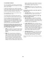
Page 24: ...when you plug in the power cord press the power switch into the reset position and insert the key into the console However when you remove the key the displays will remain lit although the buttons wi...

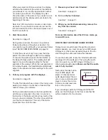
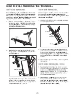
Page 25: ...sure that the latch knob is locked in the storage position Moving the treadmill may require two people 1 Hold the frame and one of the handrails and place one foot against a wheel 2 Pull back on the...

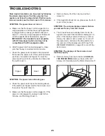
Page 26: ...the switch back in SYMPTOM The power turns off during use a Check the power switch see the drawing above If the switch has tripped wait for five minutes and then press the switch back in b Make sure...

Page 27: ...emove the key from the console SYMPTOM The walking belt slows when walked on a Use only a surge suppressor that meets all of the specifications described on page 17 b If the walking belt is overtighte...

Page 28: ...il the walking belt is centered b If the walking belt slips when walked on first re move the key and UNPLUG THE POWER CORD Using the hex key turn both idler roller screws clockwise 1 4 of a turn When...

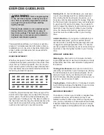
Page 29: ...c Exercise If your goal is to strengthen your cardiovascular system you must perform aerobic exercise which is activity that requires large amounts of oxygen for prolonged periods of time For aerobic...

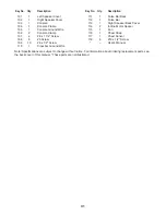
Page 30: ...43 1 Caution Decal 44 1 Walking Platform 45 1 Walking Belt 46 2 Belt Guide 47 1 Left Speaker Back Cover 48 4 Cable Tie 49 1 Drive Roller Pulley 50 1 Magnet 51 1 Reed Switch Clip 52 1 Reed Switch 53 1...

Page 31: ...ot illustrated 101 1 Left Speaker Cover 102 1 Right Speaker Cover 103 1 Console 104 1 Console Frame 105 1 Console Ground Wire 106 2 Console Clamp 107 4 8 x 1 1 4 Screw 108 8 3 Screw 109 10 6 x 1 2 Scr...

Page 32: ...9 50 14 51 21 35 26 45 12 2 10 10 48 23 15 34 30 59 61 15 30 34 59 38 39 40 41 14 39 41 39 41 38 39 41 38 38 2 2 2 23 19 46 43 42 44 21 2 41 39 38 39 41 38 39 41 38 14 39 41 38 40 2 2 34 30 59 2 14 14...

Page 33: ...33 66 10 76 77 74 2 68 75 10 2 73 65 2 2 2 72 74 2 2 2 78 62 86 2 2 2 86 58 118 118 118 118 118 68 68 2 67 67 33 29 69 33 70 16 114 71 33 33 71 86 86 86 EXPLODED DRAWING B Model No NTL12011 0 R1211B...

Page 34: ...3 92 92 7 13 8 90 77 7 13 81 82 83 14 92 8 2 33 91 91 97 14 14 14 94 7 7 91 22 22 10 81 4 32 9 37 4 37 107 87 87 79 112 1 107 1 111 1 1 1 1 32 9 84 11 5 107 98 10 110 80 85 11 5 1 1 EXPLODED DRAWING C...

Page 35: ...105 10 103 109 115 1 64 93 27 1 1 1 1 36 1 1 1 1 101 2 47 108 28 113 28 1 109 109 2 99 2 2 2 2 1 102 25 31 2 2 2 2 2 2 2 2 2 2 2 99 2 116 117 108 108 108 108 108 109 109 109 EXPLODED DRAWING D Model...

Page 36: ...xtend to freight damage to the product This warranty will automatically be voided if the product is used as a store display model if the product is purchased or transported outside the USA if all inst...

Reviews: