background image

13

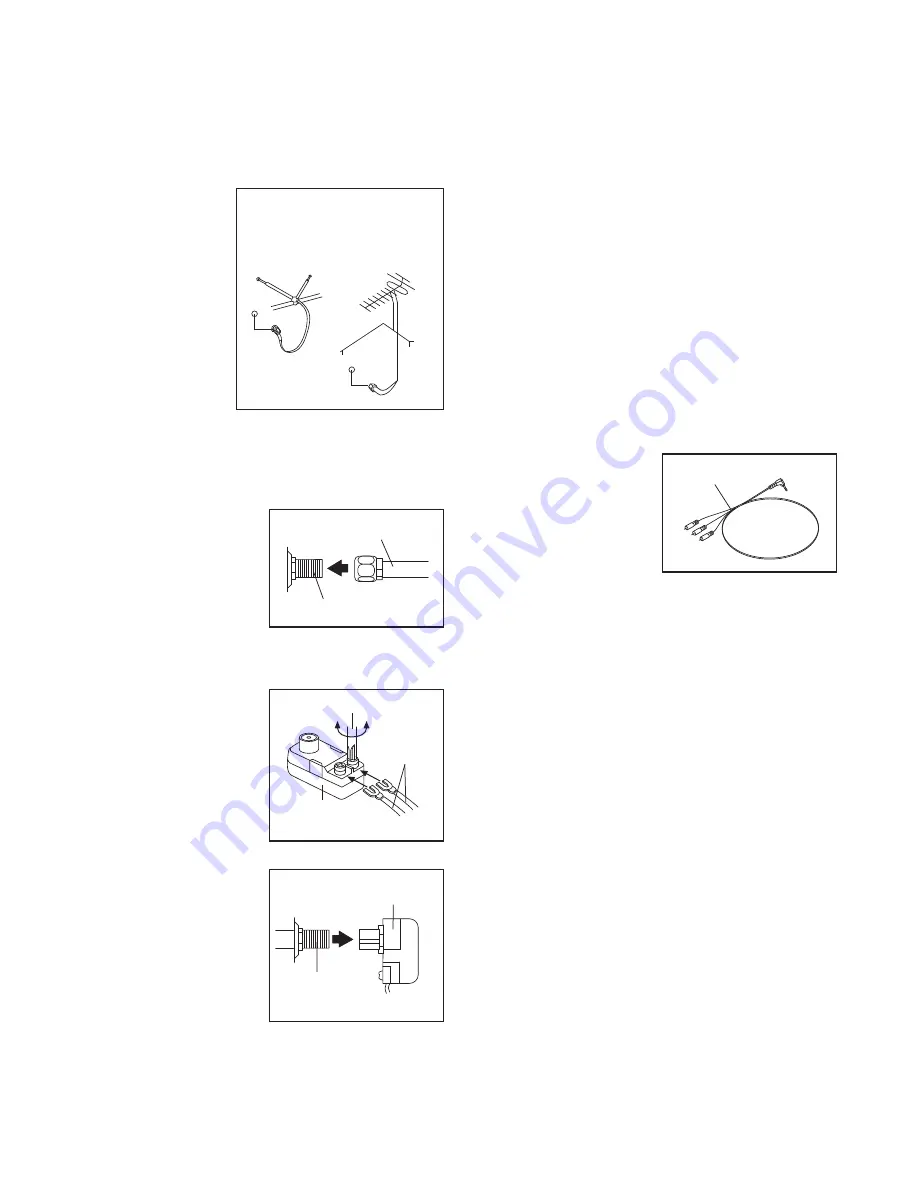
HOW TO CONNECT AN ANTENNA

Place an indoor

VHF antenna or an

outdoor combina-

tion VHF/UHF an-

tenna in the desired

location. Outdoor

antennas are sub-

ject to weathering

that can reduce sig-

nal quality. Inspect

your outdoor an-

tenna and the lead-

in wiring before

connecting the an-

tenna.

75 Ohm CATV Cable

1. Connect the 75 ohm

CATV cable from the

antenna to the 75

ohm terminal on the

treadmill frame near

the power cord.

300 Ohm Flat Wire

1. Connect the 300

ohm flat wire from

the antenna to a 300

ohm to 75 ohm

adapter.

2. Push the 300 ohm to

75 ohm adapter onto

the 75 ohm terminal

on the treadmill

frame near the power

cord.

HOW TO CONNECT AN EXTERNAL SOURCE

USING A CATV CABLE

1. Connect one end of a 75 ohm CATV cable to the

75 ohm output jack on your external source.

2. Plug in the power cord of your external source.

See your external source userʼs manual for proper

grounding instructions.

3. Connect the 75 ohm CATV cable to the 75 ohm

terminal on the treadmill frame near the power

cord. See the drawing at the left.

HOW TO CONNECT A VCR OR DVD PLAYER

USING THE 96" A/V WIRE

1. Connect the three-

pronged end of the

96" A/V Wire (101) to

your VCR or DVD

player.

2. Plug in the power cord of your VCR or DVD player.

See your VCR or DVD player userʼs manual for

proper grounding instructions.

3. Connect the 96" A/V Wire (101) to the audio/video

input jack on the treadmill frame near the power

cord.

300 to 75

Ohm Adapter

Screwdriver

300

Ohm Flat

Wire

101

75 Ohm Terminal

75 Ohm CATV Cable

Outdoor

Combination

VHF/UHF

Antenna

Indoor

VHF

Antenna

Before operating the television, you must connect an antenna or a 75 ohm CATV cable to the 75 ohm ter-

minal or the 96" A/V Wire to the audio/video input jacks.

Note: Use a CATV cable to connect to an external

source such as a cable box, satellite TV box, VCR, or analog cable. No CATV cable, antenna, or adapter is in-

cluded.

75 Ohm

Terminal

300 to 75 Ohm Adapter

Summary of Contents for Commercial CT

Page 1: ...ber in the space above for reference QUESTIONS If you have questions or if there are damaged or missing parts please contact us at the numbers or addresses listed below Call 08457 089 009 Outside UK 0...

Page 2: ...WING 39 ORDERING REPLACEMENT PARTS Back Cover RECYCLING INFORMATION Back Cover This drawing shows the locations of the warning de cals If a decal is missing or illegible call the telephone number on t...

Page 3: ...the power cord see page 14 plug the power cord into an earthed cir cuit No other appliance should be on the same circuit When replacing the fuse an ASTA approved BS1362 type should be fitted to the fu...

Page 4: ...presentative only 26 Do not store the television in temperatures below 40 F 40 C or above 140 F 60 C Do not operate the television in temperatures below 23 F 5 C or above 90 F 35 C 27 To protect the t...

Page 5: ...ill or the television ask the service technician to perform safety checks to con firm that the unit is in proper operating condi tion Use No 10 AWG 5 3 mm2 copper No 8 AWG 8 4 mm2 aluminum No 17 AWG 1...

Page 6: ...using the treadmill If you have questions after read ing this manual please see the front cover of this man ual To help us assist you note the product model number and serial number before contacting...

Page 7: ...end of this manual The number following the parentheses is the quantity needed for assembly Note If a part is not in the hardware kit check to see if it has been preassembled To avoid damaging plastic...

Page 8: ...Right Upright 117 Wire Tie 2 88 86 2 8 86 88 3 Hold Left Upright 85 near the Left Base Cover 118 See the inset drawing Make sure that the wire tie in the Left Upright is extending from the hole as sho...

Page 9: ...CONNECTORS ARE NOT CONNECTED PROPERLY THE CONSOLE MAY BE DAMAGED WHEN THE POWER IS TURNED ON Remove the wire tie from the Upright Wire 86 Remove the wire tie from the 50 TV Cable 81 and the 50 A V Wi...

Page 10: ...o ground wires extending from the console assembly Set the console assembly on the handrail as sembly If necessary move the wires so that the console assembly sits flat on the handrail as sembly Be ca...

Page 11: ...ardboard stands as shown Have the second person hold the treadmill to prevent it from moving forward or backward Firmly tighten the four 3 8 x 3 3 4 Patch Bolts 2 With the help of a second person lowe...

Page 12: ...00 are pressed firmly into the console assembly 13 Console Assembly 90 100 11 Orient the Storage Latch 78 so that the large barrel and the Latch Knob 77 are in the posi tions shown Remove the tie from...

Page 13: ...user s manual for proper grounding instructions 3 Connect the 75 ohm CATV cable to the 75 ohm terminal on the treadmill frame near the power cord See the drawing at the left HOW TO CONNECT A VCR OR DV...

Page 14: ...See drawing 2 Press the pins on the power cord into the metal clips in the adapter as shown Close the adapter cover over the end of the power cord and tighten the screw in the adapter IMPORTANT Make...

Page 15: ...iFit cards containing workouts de signed to help you achieve specific fitness goals For example lose unwanted pounds with the 8 week Weight Loss workout iFit workouts automatically con trol the tread...

Page 16: ...play speed and distance in either kilometers or miles To find out which unit of measurement is selected or to change the unit of mea surement see THE INFORMATION MODE on page 28 For simplicity all ins...

Page 17: ...p pulse sensor and the optional chest pulse sensor at the same time the console will not display your heart rate accurately See page 29 for information about the optional chest pulse sensor Before usi...

Page 18: ...ent At the end of each segment a series of tones will sound and the next segment of the profile will begin to flash The new speed and incline settings will appear in the displays for a few seconds If...

Page 19: ...eg ment To program speed and incline settings for the first segment simply adjust the speed and in cline of the treadmill as desired by pressing the speed and incline buttons When the first segment of...

Page 20: ...workout will function in the same way as a preset workout see step 3 on page 18 If desired you can redesign the workout while using it To change the speed setting or the in cline setting for the curr...

Page 21: ...tomatically increase or decrease to bring your heart rate closer to the tar get heart rate setting If your pulse is not detected during the program the letters PLS will flash in the display and the sp...

Page 22: ...e workout A mo ment after you press the button the treadmill will automatically adjust to the first speed and incline settings of the workout Hold the handrails and begin walking During the workout a...

Page 23: ...d for optimal recep tion see HOW TO CONNECT AN ANTENNA on page 13 4 Press the TV AV button to select an input mode Select an input mode by pressing the TV AV button on the remote control repeatedly un...

Page 24: ...a list of channels Note You can also view this list by pressing the PRLIST button on the console Press the EPG button to view the electronic program guide while in DTV mode Press the Info button to vi...

Page 25: ...image settings Adjust the brightness contrast and colour of the image using the and buttons Adjust the rotation of the screen with the Up Down and Mirror options Select a screen size Select the reset...

Page 26: ...ngs Note The preset settings option is available only while in the TV mode Adjust the settings for a specific channel by select ing that channel number in the Position option Turn on or turn off the R...

Page 27: ...have not set a password yet the old password is 0000 Your new password must be four numbers long If you forget your password select the factory reset menu option Select the Video menu option Select Au...

Page 28: ...to change the unit of measurement if de sired The Time display will show the total number of hours the treadmill has been used The Distance display will show the total number of miles or kilometers t...

Page 29: ...ayer and the CD skips set the CD player on the floor or another flat sur face and not on the console THE OPTIONAL CHEST PULSE SENSOR An optional chest pulse sensor offers hands free oper ation as it t...

Page 30: ...knob is locked in the storage position To protect the floor or carpet from damage place a mat under the treadmill Keep the treadmill out of di rect sunlight Do not leave the treadmill in the stor age...

Page 31: ...e To release the latch knob it may be necessary to push the frame forward as you pull the latch knob to the left 2 Hold the metal frame firmly with both hands and lower it to the floor CAUTION To decr...

Page 32: ...r see the drawing above If the circuit breaker has tripped wait for five minutes and then press the switch to the reset position b Make sure that the power cord is plugged in If the power cord is plug...

Page 33: ...key and UNPLUG THE POWER CORD Using the hex key turn both idler roller bolts counterclockwise 1 4 of a turn When the walking belt is properly tightened you should be able to lift each edge of the walk...

Page 34: ...ly good reception is necessary If you are using an an tenna make sure that it is properly connected and adjusted for optimal reception See HOW TO CONNECT AN ANTENNA on page 13 c Check for the problems...

Page 35: ...kling sound when the volume is turned up the volume is too loud Press the Volume increase or decrease button on the remote control until the volume level is 80 percent Once the volume reaches 80 perce...

Page 36: ...your goal is to strengthen your cardiovascular system you must perform aerobic exer cise which is activity that requires large amounts of oxygen for prolonged periods of time For aerobic ex ercise adj...

Page 37: ...eft Foot 41 4 Foot Wheel 42 2 Cushion Track 43 1 Warning Decal 44 1 Walking Platform 45 2 Platform Cushion 46 2 Belt Guide 47 1 Walking Belt 48 1 Reed Switch 49 2 Motor Hood Mount 50 2 Lift Arm Spacer...

Page 38: ...it Demo Card 121 1 5 32 Hex Key 122 1 18 Audio Wire 123 1 Remote Control 124 1 Magnet 125 1 Filter Wire 126 1 Console 127 1 TV 128 1 Console Fan 129 4 3 x 1 4 Screw 130 2 Speaker 131 1 4 Ground Wire w...

Page 39: ...7 22 23 50 51 53 22 60 15 37 31 61 125 57 17 26 62 9 18 41 40 26 18 9 41 39 14 7 14 7 45 45 65 4 3 48 58 4 3 14 14 14 14 14 14 14 14 31 16 16 37 87 26 26 42 42 121 25 34 25 133 131 33 33 55 28 33 28 2...

Page 40: ...68 9 12 67 11 9 71 70 7 66 7 7 7 36 36 72 73 75 78 5 9 6 9 79 77 21 21 21 21 21 21 74 69 76 83 EXPLODED DRAWING B Model No NETL14708 0 R0109A 40...

Page 41: ...16 24 112 24 9 112 9 113 27 113 27 113 86 86 7 7 27 113 7 7 7 7 7 7 81 117 8 2 8 2 8 114 35 29 38 80 85 1 8 80 81 87 111 1 8 1 8 1 8 9 9 32 32 27 25 25 32 112 118 116 32 EXPLODED DRAWING C Model No NE...

Page 42: ...42 105 13 13 7 7 106 109 102 7 7 7 7 7 7 7 7 7 108 107 103 13 13 104 108 107 103 25 96 EXPLODED DRAWING D Model No NETL14708 0 R0109A...

Page 43: ...97 7 13 17 13 30 17 30 92 91 93 110 101 13 122 120 119 123 7 119 7 26 17 119 17 17 127 126 129 129 128 17 17 130 17 130 17 135 137 138 139 7 17 17 17 17 17 17 17 17 17 17 17 17 17 17 17 17 EXPLODED DR...

Page 44: ...t s see the PART LIST and the EXPLODED DRAWING near the end of this manual RECYCLING INFORMATION This electronic product must not be disposed of in municipal waste To preserve the environment this pro...

Reviews: