background image

5

4

33 

37

53

33 

37

6

Before beginning assembly, carefully read the fol-
lowing information and instructions:

• Assembly requires two persons.

• Because of its size, the weight bench should be

assembled in the location where it will be used.
Make sure that there is enough clearance to walk
around the weight bench as you assemble it.

• Place all parts in a cleared area and remove the

packing materials. Do not dispose of the packing
materials until assembly is completed. 

• For help identifying small parts, use the PART

IDENTIFICATION CHART on page 5.

• As you assemble the weight bench, make sure all

parts are oriented as shown in the drawings.  

• Tighten all parts as you assemble them, unless

instructed to do otherwise. 

• Assembly requires the included hex key(s)             

and the following tools (not included): 

two adjustable wrenches

one rubber mallet

one standard screwdriver

one Phillips screwdriver

Assembly may be more convenient if you have a
socket set, a set of open-end or closed-end
wrenches, or a set of ratchet wrenches.

ASSEMBLY

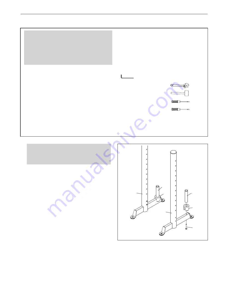
1.

Identify the Left Upright (4), which is marked with
an “L” sticker. Attach a Weight Tube Sleeve (37)
and a Weight Tube (33) to the Left Upright with
an M10 x 125mm Screw (53).

Attach the other Weight Tube Sleeve (37) and
Weight Tube (33) to the Right Upright (5) in
the same way.  

1

Before beginning assembly, make sure
that you understand the information in the
box above. 

Make Assembly Easier

Everything in this manual is designed to ensure
that the weight bench can be assembled suc-
cessfully by almost anyone. By setting aside
plenty of time, assembly will go smoothly. 

Summary of Contents for Competition 831.15718.0

Page 1: ...nd serial number see the drawing above before contacting us CALL TOLL FREE 1 888 825 2588 Mon Fri 6 a m 6 p m MST Sat 8 a m 4 p m MST ON THE WEB www nordictrackservice com CAUTION Read all precautions...

Page 2: ...G REPLACEMENT PARTS Back Cover LIMITED WARRANTY Back Cover TABLE OF CONTENTS The decals shown here have been applied in the locations shown If a decal is missing or illegible call the tele phone numbe...

Page 3: ...ture and dust Place the weight bench on a level surface with a mat beneath it to protect the floor or carpet Make sure that there is enough clearance around the weight bench to mount dismount and use...

Page 4: ...ou want For your benefit read this manual carefully before using the weight bench If you have questions after reading this manual see the front cover of this manu al To help us assist you please note...

Page 5: ...Screw 56 M14 Washer 68 M6 x 16mm Screw 51 M6 x 65mm Screw 59 M14 Nylon Locknut 50 M12 Nylon Locknut 64 See the drawings below to identify small parts used in assembly The number in parentheses by eac...

Page 6: ...ucted to do otherwise Assembly requires the included hex key s and the following tools not included two adjustable wrenches one rubber mallet one standard screwdriver one Phillips screwdriver Assembly...

Page 7: ...2 13 44 1 3 Orient the Seat Carriage 13 and the Frame 1 as shown and slide the Seat Carriage onto the Frame Next pull the Seat Carriage Knob 44 slide the Seat Carriage 13 to the desired position and...

Page 8: ...lon Locknuts 67 See the inset drawing Attach the Backrest Bumper 36 to the Cross Frame 2 with an M4 x 25mm Self tapping Screw 54 1 2 57 65 67 65 5 54 2 36 56 7 Apply some of the included grease to an...

Page 9: ...ylon Locknut 64 Do not overtighten the Nylon Locknut the Backrest Frame must pivot easily 18 60 Grease Grease 68 8 68 7 1 50 51 12 70 19 59 9 13 62 64 6 10 Grease an M12 x 90mm Bolt 62 Attach the Seat...

Page 10: ...lt Set Make sure that the barrel of the Bolt Set is inserted through both sides of the bracket on the Front Leg 12 Insert the Long Pad Tube 8 into the Front Leg 3 Slide two Foam Pads 21 onto the Long...

Page 11: ...Upright Insert the attached Upright Pin 41 into the Weight Rest and one of the adjustment holes in the Right Upright Attach the other Safety Spotter 17 and the other Weight Rest 16 to the Left Uprigh...

Page 12: ...t 19 and the Backrest 18 pull the Seat Carriage Knob 44 slide the Seat Carriage 13 to the desired position and then release the Seat Carriage Knob Move the Seat Carriage back and forth slightly to mak...

Page 13: ...ach the Curl Frame 10 to the Leg Lever 11 with the Curl Bar Pin 45 9 20 3 ATTACHING THE CURL PAD To use the Curl Pad 20 insert the Curl Post 9 into the Front Leg 3 Secure the Curl Post with the Curl K...

Page 14: ...r 17 hold the Safety Spotter and pull out the attached Upright Pin 41 Move the Safety Spotter to the desired height and insert the Upright Pin into the Safety Spotter and one of the adjustment holes i...

Page 15: ...ursday Rest from both strength training and aerobic exercise for at least one full day each week to give your body time to regenerate The combination of strength training and aerobic exer cise will re...

Page 16: ...without strain Stretching at the end of each workout is an effective way to increase flexibility STAYING MOTIVATED For motivation keep a record of each workout List the date the exercises performed t...

Page 17: ...17 NOTES...

Page 18: ...48mm Round Inner Cap 32 1 Weight Stop 33 3 Weight Tube 34 6 Foot 35 1 Leg Lever Bumper 36 1 Backrest Bumper 37 2 Weight Tube Sleeve 38 4 Seat Backrest Bushing 39 1 Curl Post Bushing 40 1 Curl Knob 41...

Page 19: ...28 28 28 27 28 28 28 29 29 30 47 31 32 33 34 34 34 34 34 35 36 37 37 31 33 33 31 39 40 41 41 41 41 42 43 43 42 44 45 46 49 51 58 52 53 53 54 53 55 55 56 57 54 55 52 52 52 52 51 59 60 61 54 54 64 65 5...

Page 20: ...rge This warranty does not extend to any product or damage to a product caused by or attributable to freight damage abuse misuse improper or abnormal usage or repairs not provided by an ICON authorize...

Reviews: