30
Next, loosen, but do not remove, the indicated M4 x
16mm Screw (93). Slide the Reed Switch (69) slightly
toward or away from the Magnet (75). Then, retighten
the M4 x 16mm Screw.
Plug in the power cord and rotate the large pulley for
a moment. Repeat these actions until the console
displays correct feedback. When the reed switch is
correctly adjusted, reattach the access cover.
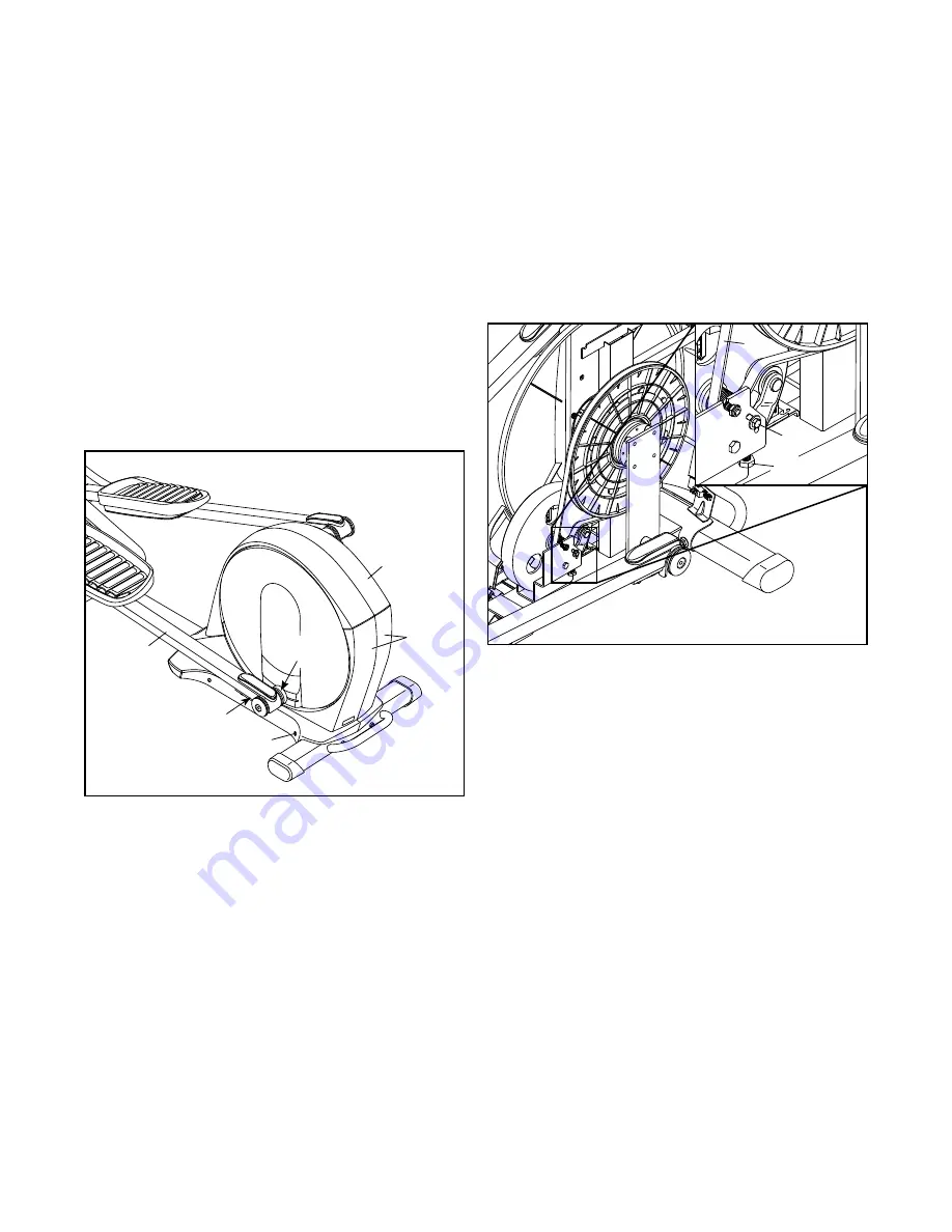
HOW TO ADJUST THE DRIVE BELT
If you can feel the pedals slip while you are pedaling,
even when the resistance is adjusted to the highest
level, the drive belt may need to be adjusted.
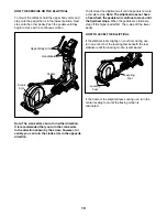
To adjust the drive belt, first unplug the power cord.
Using a flat screwdriver, release the tabs on the Top
Cover (20) and pry the Top Cover upward off the
elliptical.
Next, lift the Latch (117) on the underside of the Left
Pedal Arm (13), and then lift the Left Pedal Arm off the
left Sleeve (136).
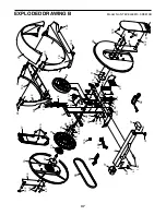
See EXPLODED DRAWING B on page 37. Remove
the M4 x 16mm Screws (93) and the M4 x 42mm
Screws (124) from the Right and Left Shields (18, 19).
Make sure to note which size Screws come from
which holes. Then, carefully remove the Left Shield.
Loosen the Pivot Screw (97). Tighten the Belt
Adjustment Screw (85) until the Drive Belt (38) is tight.
When the Drive Belt is tight, tighten the Pivot Screw.
When you are finished, reattach the left shield, replace
the left pedal arm, and reattach the access cover.
Then, plug in the power cord.
13
117
19, 18
124
136
85
38
97
20
Summary of Contents for E 11.6 NTEVEL99813.0
Page 33: ...33 NOTES...

