background image

28

 HOW TO USE THE WIRELESS NETWORK MODE

The console features a wireless network mode that 
allows you to set up a wireless network connection.

1.  Select the settings main menu.


See step 1 on page 26.

2.  Select the wireless network mode.


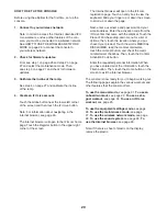
  In the settings main menu, touch the Wireless 
Network button to enter the wireless network mode.

3. Enable 

Wi-Fi.


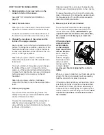
 Make sure that the Wi-Fi checkbox is marked with 
a green checkmark. If it is not, touch the Wi-Fi 
menu option once and wait for a few seconds. The 
console will search for available wireless networks. 

4.  

Set up and manage a wireless network 
connection.


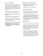
 When Wi-Fi is enabled, the screen will show a list 
of available networks. Note: It may take several 
seconds for the list of wireless networks to appear.


 Make sure that the checkbox on the Network 
notification menu option is marked with a green 
checkmark to have the console notify you when a 
wireless network is within range and available.


 Note: You must have your own wireless network 
and an 802.11b/n router with SSID broadcast 
enabled (hidden networks are not supported). 


 When a list of networks appears, touch the desired 
network. Note: You will need to know your network 
name (SSID). If your network has a password, you 
will also need to know the password.


 An information box will ask if you want to connect 
to the wireless network. Touch the Connect button 
to connect to the network or touch the Cancel but-
ton to return to the list of networks. If the network 
has a password, touch the password entry box. A 
keyboard will appear on the screen. To view the 
password as you type it, touch the Show Password 
checkbox.


 To use the keyboard, see HOW TO USE THE 
TOUCH SCREEN on page 19.


 When the console is connected to your wireless 
network, the WiFi menu option at the top of the 
screen will display the word CONNECTED. Then, 
press the Back button on the screen to return to the 
wireless network mode.


 To disconnect from a wireless network, select the 
wireless network and then touch the Forget button.


 If you are having problems connecting to an 
encrypted network, make sure that your password 
is correct. Note: Passwords are case-sensitive.


 Note: The iFit Live mode supports unsecured and 
secured (WEP, WPA, and WPA2) encryption. A 
broadband connection is recommended; perfor-
mance depends on connection speed. 


 Note: If you have questions after following 
these instructions, go to www.iFit.com/support 
for assistance.

5.  Exit the wireless network mode.


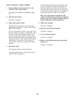
 To exit the wireless network mode, press the Back 
button on the console.

Summary of Contents for E 15.0 Elliptical

Page 1: ...space above for reference www nordictrack com QUESTIONS If you have questions or if parts are damaged or missing DO NOT CONTACT THE STORE please contact Customer Care IMPORTANT Please register this p...

Page 2: ...l size TABLE OF CONTENTS WARNING DECAL PLACEMENT FREEMOTION is a registered trademark of ICON IP Inc WARNING DECAL PLACEMENT 2 IMPORTANT PRECAUTIONS 3 BEFORE YOU BEGIN 4 PART IDENTIFICATION CHART 5 AS...

Page 3: ...each side To protect the floor or carpet from dam age place a mat under the elliptical 7 Inspect and properly tighten all parts regu larly Replace any worn parts immediately 8 Keep children under age...

Page 4: ...make your workouts at home more effective and enjoyable For your benefit read this manual carefully before you use the elliptical If you have questions after reading this manual please see the front c...

Page 5: ...12 8 x 3 4 Screw 123 11 PART IDENTIFICATION CHART Use the drawings below to identify the small parts needed for assembly The number in parentheses below each drawing is the key number of the part fro...

Page 6: ...Remove the screws not shown and the ship ping bracket not shown from the front of the Frame 1 Discard the screws With the help of a second person place the ship ping bracket not shown under the front...

Page 7: ...x 75mm Screws 119 Then remove and discard the shipping bracket not shown 4 5 2 117 4 Orient the Rear Stabilizer Cover 2 as shown Press the Mounts 117 on the underside of the Rear Stabilizer Cover 2 in...

Page 8: ...4 on the Frame 1 Attach the Upright 4 with four M8 x 19mm Screws 82 and four M8 Star Washers 122 6 Avoid pinching the Main Wire 110 1 82 4 122 110 7 56 75 7 Orient the Lower Upright Cover 56 as shown...

Page 9: ...p your fingers clean apply some of the included grease to the Pivot Axle 35 and to two Wave Washers 95 only one is shown Insert the Pivot Axle 35 through the Upright 4 and then center it Tip It may be...

Page 10: ...5 11 Identify the Right Pedal 49 and the Right Pedal Arm 58 which are marked with Right stickers and orient them as shown Attach the Right Pedal 49 to the Right Pedal Bracket 139 on the Right Pedal Ar...

Page 11: ...Upper Body Arm 61 into the Right Upper Body Leg 36 until step 14 Orient the Right Upper Body Leg 36 as shown Apply grease to the axle on the Right Upper Body Leg Slide the Pedal Arm Flex Bracket 136...

Page 12: ...n the other side of the elliptical See step 13 Tighten the M8 x 16mm Screws 120 67 68 36 123 123 15 Attach the Right Inner Cover 68 to the Right Upper Body Arm 61 with a 8 x 3 4 Screw 123 Identify the...

Page 13: ...the Console 7 16 7 17 Tip Avoid pinching the wires Attach the Console 7 to the Upright 4 with four 8 x 1 2 Screws 124 18 Avoid pinching the wires Avoid pinching the wires 124 124 4 18 Orient the Rear...

Page 14: ...is com pleted some extra parts may be left over Place a mat beneath the elliptical to protect the floor 19 Orient the Front Upright Cover 91 as shown Press the Front Upright Cover 91 into the Rear Upr...

Page 15: ...tures above 122 F 50 C or below 14 F 10 C Do not excessively bend or stretch the sensor when using or storing the heart rate monitor To clean the sensor use a damp cloth and a small amount of mild soa...

Page 16: ...adapter is used it must be held in place by a metal screw Some 2 pole receptacle outlet box covers are not grounded Contact a qualified electrician to determine if the outlet box cover is grounded be...

Page 17: ...pedal Push the pedals until they begin to move with a continuous motion Note The crank arms can turn in either direction It is recommended that you turn the crank arms in the direction shown by the a...

Page 18: ...the incline of the ramp and prompts you to vary your pedaling speed as it guides you through an effective workout You can also set a time distance calorie or rpm goal Eight iFit Live demo workouts are...

Page 19: ...step 4 on page 21 However you cannot zoom in and out by sliding your fingers on the screen The screen is not pressure sensitive You do not need to press hard on the screen To type information into a...

Page 20: ...ard Slide your finger up or down the screen to scroll up or down the page Next enter a username and password and your e mail address Enter the activation code from the iFit Live flier that came with t...

Page 21: ...mation is shown To select the desired display mode simply flick or slide the screen see page 19 You can also view additional workout information by touching the red boxes on the screen If desired adju...

Page 22: ...urn on the console See HOW TO TURN ON THE POWER on page 19 2 Select an onboard workout To select an onboard workout touch the Runner button in the lower left corner of the screen The workouts menu wil...

Page 23: ...ment Note The calorie goal is an estimate of the number of calories that you will burn during the workout The actual number of calories that you burn will depend on your metabolic rate In addition if...

Page 24: ...r of calories you will burn during the workout 4 Start the workout Touch the Start button to start the workout The workout will function in the same way as the manual mode see page 21 The workout will...

Page 25: ...see page 24 Note You can also press one of the iFit Live buttons on the console To switch users within the account touch the User button at the bottom of the screen Before some workouts will download...

Page 26: ...nauthorized users from using the elliptical Touch the Passcode button To enable a passcode touch the Enable checkbox Then enter a 4 digit passcode of your choice Touch Save to use this passcode Touch...

Page 27: ...he update should begin automatically The screen will show the progress of the update When the update is complete the elliptical will turn off and then turn back on If it does not press the power switc...

Page 28: ...know your network name SSID If your network has a password you will also need to know the password An information box will ask if you want to connect to the wireless network Touch the Connect button t...

Page 29: ...ERNET BROWSER Note To use the Internet browser you must have access to a wireless network including an 802 11b n router with SSID broadcast enabled hidden networks are not supported To open the Intern...

Page 30: ...equipment does cause harmful interference to radio or television reception which can be determined by turning the equipment off and on try to correct the interference by one or more of the following m...

Page 31: ...of the ramp see step 4 on page 27 HOW TO GREASE THE ROLLERS See the EXPLODED DRAWING near the end of this manual If the Rollers 51 squeak when moving on the Tracks 11 apply a small amount of white ma...

Page 32: ...m the right disc the front stabilizer cover the shield cover and the lower upright cover HOW TO ADJUST THE REED SWITCH If the console does not display correct feedback the reed switch should be adjust...

Page 33: ...c Exercise If your goal is to strengthen your cardiovascular system you must perform aerobic exercise which is activity that requires large amounts of oxygen for prolonged periods of time For aerobic...

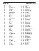
Page 34: ...Pedal Arm Cap 53 6 Axle Cover 54 1 Left Outer Cover 55 1 Left Inner Cover 56 1 Lower Upright Cover 57 4 Roller Arm Bushing 58 1 Right Pedal Arm 59 4 Axle Bushing 60 2 Crank Arm Cover 61 1 Right Upper...

Page 35: ...Lift Motor Bushing 132 2 1 Grommet 133 4 Crank Arm Bushing 134 1 Ramp Shield 135 2 Roller Arm Flex Bracket 136 2 Pedal Arm Flex Bracket 137 8 Flex Bracket Cover 138 1 Left Pedal Bracket 139 1 Right P...

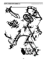
Page 36: ...133 80 35 91 75 56 52 144 142 120 104 123 104 104 71 128 60 76 104 104 104 104 73 104 104 104 104 104 126 148 145 137 141 99 104 137 147 138 140 104 104 137 99 135 147 137 104 146 53 120 46 123 55 70...

Page 37: ...120 120 102 102 42 20 105 104 104 149 149 72 30 65 120 98 31 30 132 105 72 30 98 120 92 92 119 5 13 92 116 34 92 6 116 34 99 84 16 17 1 15 40 83 125 32 32 97 85 86 78 85 86 78 19 43 43 99 99 106 105 9...

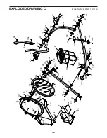
Page 38: ...28 104 104 104 104 133 45 133 53 98 120 41 71 104 104 104 104 126 127 127 121 49 123 68 70 67 120 98 70 102 123 96 61 95 135 139 144 144 142 146 143 145 141 140 104 137 147 99 137 104 137 137 147 104...

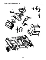
Page 39: ...G D Model No NTEL91411 1 R1111A 79 9 3 11 93 93 10 127 127 127 115 117 115 117 117 115 115 79 79 79 127 7 124 124 69 4 30 63 30 82 123 123 122 104 104 117 117 117 117 117 117 2 110 112 150 114 8 134 1...

Page 40: ...t extend to freight damage to the product This warranty will automatically be voided if the product is used as a store display model if the product is purchased or transported outside the USA if all i...

Reviews: