background image

18

 HOW TO USE THE MANUAL MODE

1.   Begin pedaling or press any button on the 

console to turn on the console.


 When you turn on the console, the display will turn 
on. The console will then be ready for use.

2.  Select the manual mode.


 Press the Manual Control button on the console to 
select the manual mode. 


 If a wireless iFit Live module is not inserted into 
the console and connected to iFit Live, the manual 
mode will be selected automatically.

3.  Change the resistance of the pedals as desired.


 As you pedal, change the resistance of the pedals 
by pressing the Resistance increase and decrease 
buttons.


 Note: After you press a button, it will take a 
moment for the pedals to reach the selected resis-
tance level. 

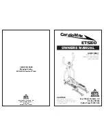
 4.  Follow your progress with the display.


 The display can show the following workout 
information:


Calories (Cals.)

——This display mode will show the 

approximate number of calories you have burned.


Calories per Hour (Cals./Hr)

——This display mode 

will show the approximate number of calories you 
are burning per hour.


Distance (Dist.)

——This display mode will show 

the distance that you have pedaled in miles or 
kilometers. 


Pulse

——This display mode will show your heart rate 

when you use the handgrip heart rate monitor (see 
step 5 on page 19).


 Resistance (Resist.)

——This display mode will 

show the resistance level of the pedals for a few 
seconds each time the resistance level changes. 


RPM

——This display mode will show your pedaling 

speed in revolutions per minute (rpm).


Stride

——This display mode will show the total num-

ber of strides you have pedaled.


Time

——When the manual mode is selected, this 

display mode will show the elapsed time. When an  
onboard workout is selected, this display mode will 
show the time remaining in the workout.


 The matrix offers several display tabs. Press the 
Display button until the desired tab is shown. You 
can also press the increase and decrease buttons 
next to the Enter button.


Speed

——This tab will show a profile of the speed 

settings of the workout. A new segment will appear 
at the end of each minute.


 My Trail

——This tab will show a track that represents 

1/4 mile (400 m). As you exercise, the flashing 
rectangle will show your progress. The My Trail tab 
will also show the number of laps you complete. 


Calorie

——This tab will show the approximate 

amount of calories you have burned. The height of 
each segment represents the amount of calories 
burned during that segment.


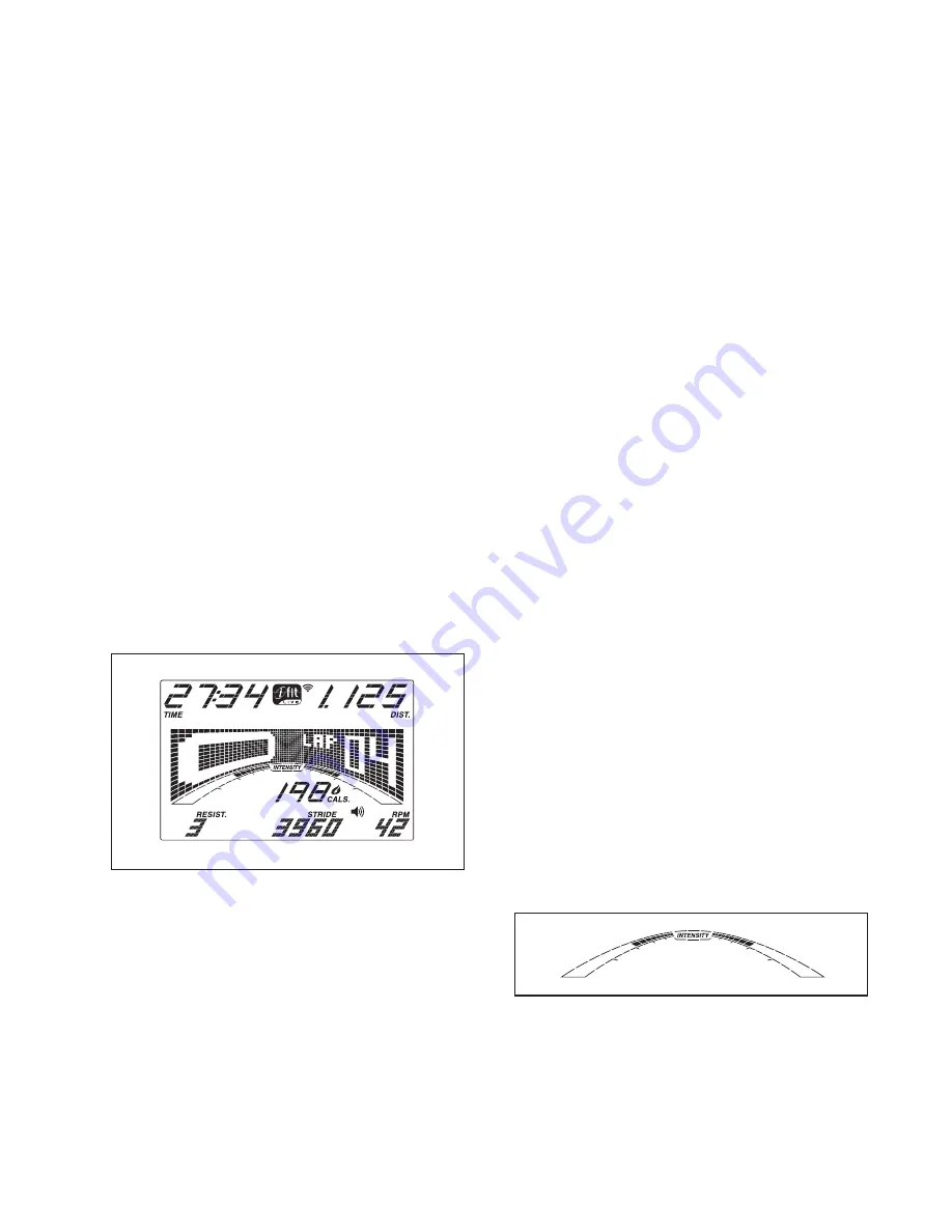
 As you exercise, the workout intensity level bar 
will indicate the approximate intensity level of your 
exercise. 

Summary of Contents for E 5.5 Elliptical

Page 1: ...e the serial number in the space above for reference QUESTIONS If you have questions or if parts are damaged or missing DO NOT CONTACT THE STORE please contact Customer Care IMPORTANT Please register...

Page 2: ...ement decal Apply the decal in the loca tion shown Note The decal s may not be shown at actual size TABLE OF CONTENTS WARNING DECAL PLACEMENT 2 IMPORTANT PRECAUTIONS 3 BEFORE YOU BEGIN 4 PART IDENTIFI...

Page 3: ...each side To protect the floor or carpet from dam age place a mat under the elliptical 7 Inspect and properly tighten all parts regu larly Replace any worn parts immediately 8 Keep children under age...

Page 4: ...this manual please see the front cover of this manual To help us assist you note the product model number and serial number before contacting us The model number and the location of the serial number...

Page 5: ...w 112 6 M10 x 120mm Screw 100 4 PART IDENTIFICATION CHART Use the drawings below to identify the small parts needed for assembly The number in parentheses below each drawing is the key number of the p...

Page 6: ...do not use power tools ASSEMBLY 2 Orient the Front Stabilizer 3 as shown While a second person lifts the Frame 1 attach the Front Stabilizer 3 to the Frame with two M10 x 120mm Screws 100 and two M10...

Page 7: ...Screws 82 4 Orient the Upright 5 and the Top Cover 23 as shown Slide the Top Cover upward onto the Upright Have a second person hold the Upright 5 and the Top Cover 23 near the Frame 1 Connect the Upr...

Page 8: ...1 22 yet 5 1 23 21 22 102 83 102 83 102 6 Identify the Right Upper Body Arm 8 and the Right Upper Body Leg 6 and orient them as shown Insert the Right Upper Body Arm 8 into the Right Upper Body Leg 6...

Page 9: ...right Axle 48 into the Upright 5 and center it Slide a Wave Washer 118 onto each end of the Upright Axle Slide the Right and Left Upper Body Arms 8 9 onto the Upright Axle 48 8 At the same time tighte...

Page 10: ...rm Axle 115 and to an M8 x 23mm x 1 5mm Washer 91 Next tighten an M8 x 16mm Screw 102 and an M8 x 23mm x 1 5mm Washer 91 a few turns into one end of the Short Pedal Arm Axle 115 Orient a Pedal Arm 12...

Page 11: ...ide the bracket on the Right Upper Body Leg 6 insert the Long Pedal Arm Axle 106 through both parts Tighten another M8 x 16mm Screw 102 and an M8 x 23mm x 1 5mm Washer 91 a few turns into the Long Ped...

Page 12: ...s 102 Tip Tighten the two Screws on the front of the elliptical before tightening the other four Screws Identify the Right Rear and Front Leg Covers 29 30 Attach the Right Front Leg Cover 30 to the Ri...

Page 13: ...lebar 10 as shown Have a second person hold the Handlebar near the Upright 5 Locate the Pulse Wires 79 in the Handlebar 10 Insert the Pulse Wires into the hole in the front of the Upright 5 Then pull...

Page 14: ...M4 x 16mm Screws 93 21 Attach the Console Cover 11 to the Console 33 with two M4 x 16mm Screws 93 22 Plug the Power Adapter 59 into the receptacle on the frame of the elliptical Note To plug the Power...

Page 15: ...en the elliptical is not in use the frame can be folded out of the way Hold the handle and gently lift the frame until the pivot arms fold and the frame locks in a folded position To use the elliptica...

Page 16: ...stabilizer until the rocking motion is eliminated If the frame of the elliptical flexes during use turn one or both of the leveling feet under the center of the frame until the flexing is eliminated H...

Page 17: ...features an iFit Live mode that enables the console to communicate with your wireless network through an optional iFit Live module With the iFit Live mode you can download personalized work outs creat...

Page 18: ...your heart rate when you use the handgrip heart rate monitor see step 5 on page 19 Resistance Resist This display mode will show the resistance level of the pedals for a few seconds each time the resi...

Page 19: ...ing your hands or gripping the contacts tightly When your pulse is detected a heart symbol in the calorie display will flash each time your heart beats one or two dashes will appear and then your hear...

Page 20: ...ment of the profile will begin to flash If a different resis tance level and or target speed is programmed for the next segment the resistance level and or target speed will appear in the display for...

Page 21: ...in a race that you have previously scheduled For more information on the iFit Live workouts please see www iFit com When you select an iFit Live workout the display will show the duration of the worko...

Page 22: ...decrease button to view the contrast level The currently selected contrast level will appear in the display Press the Resistance increase and decrease buttons to adjust the con trast level 5 Determine...

Page 23: ...equipment does cause harmful interference to radio or television reception which can be determined by turning the equipment off and on try to correct the interference by one or more of the following m...

Page 24: ...ole does not display correct feedback the reed switch should be adjusted To adjust the reed switch you must first remove the Top Shield 20 Using a flat screw driver release the tabs on the front and r...

Page 25: ...n the front and rear of the Top Shield 20 and then remove the Top Shield Next remove the M4 x 16mm Round Head Screws 90 and the M4 x 42mm Screws 98 from the Right and Left Shields 18 19 Make sure to n...

Page 26: ...c Exercise If your goal is to strengthen your cardiovascular system you must perform aerobic exercise which is activity that requires large amounts of oxygen for prolonged periods of time For aerobic...

Page 27: ...justment Knob 46 2 Knob Cap 47 4 Pivot Arm Bushing 48 1 Upright Axle 49 1 Left Inner Leg Cover 50 1 Left Outer Leg Cover 51 1 Right Pivot Arm 52 1 Left Pivot Arm 53 2 Adjustment Arm Spring 54 4 Adjust...

Page 28: ...M8 x 16mm Screw 103 2 M10 Locknut 104 6 M8 x 45mm Bolt 105 6 M8 Locknut 106 2 Long Pedal Arm Axle 107 2 M10 x 25mm Screw 108 2 M10 Washer 109 1 Frame Wire 110 2 M8 x 23 5mm x 1mm Washer 111 10 M6 x 1...

Page 29: ...29 EXPLODED DRAWING A 93 93 5 24 26 11 10 34 34 25 93 93 93 93 93 57 57 33 23 93 93 93 22 93 21 102 20 98 98 18 19 98 98 90 90 90 82 79 Model No NTEL06011 5 R0612A...

Page 30: ...63 108 107 86 86 87 76 73 74 94 75 75 76 87 71 84 81 72 93 70 69 60 38 16 39 40 17 16 1 17 39 40 40 102 102 102 40 120 120 120 120 41 109 92 59 13 82 83 83 83 4 37 37 41 41 88 100 93 93 3 36 36 55 56...

Page 31: ...116 117 117 115 102 111 111 117 117 116 115 102 91 112 91 102 112 119 91 102 91 102 106 91 102 91 102 57 35 9 15 12 43 53 44 111 111 45 47 47 44 52 46 53 43 47 51 45 111 111 12 14 47 46 28 27 6 29 8...

Page 32: ...ge to the product This warranty will automatically be voided if the product is used as a store display model if the product is purchased or transported outside the USA if all instructions in this manu...

Reviews: