background image

8

6

5

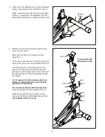
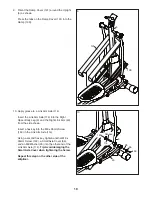
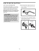
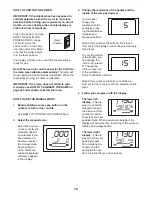
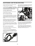
5.  Using a plastic bag to keep your fingers clean, 

apply a generous amount of the included 
grease to the Upright Axle (48) and to two Wave 
Washers (118).


Tip: Avoid damaging the Wire Harness (60).


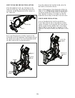
Insert the Upright Axle (48) through the Upright 
(5) and center it. Slide a Wave Washer (118) 
onto each side of the Upright Axle.


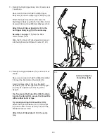
Next, identify the Right and Left Upper Body 
Legs (6, 7) and orient them as shown.


Slide the Right and Left Upper Body Legs 
(6, 7) onto the right and left sides of the Upright 
Axle (48).


Tighten an M8 x 16mm Screw (102) and an M8 
Washer (95) into each end of the Upright Axle 
(48) 

at the same time.

Avoid damaging the 

Wire Harness (60)

Grease

Grease

95

5

7

102

95

102

118

48

60

6

118

14

12

111

112

112

62

62

158

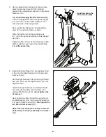
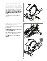
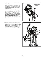
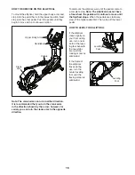
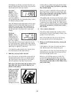
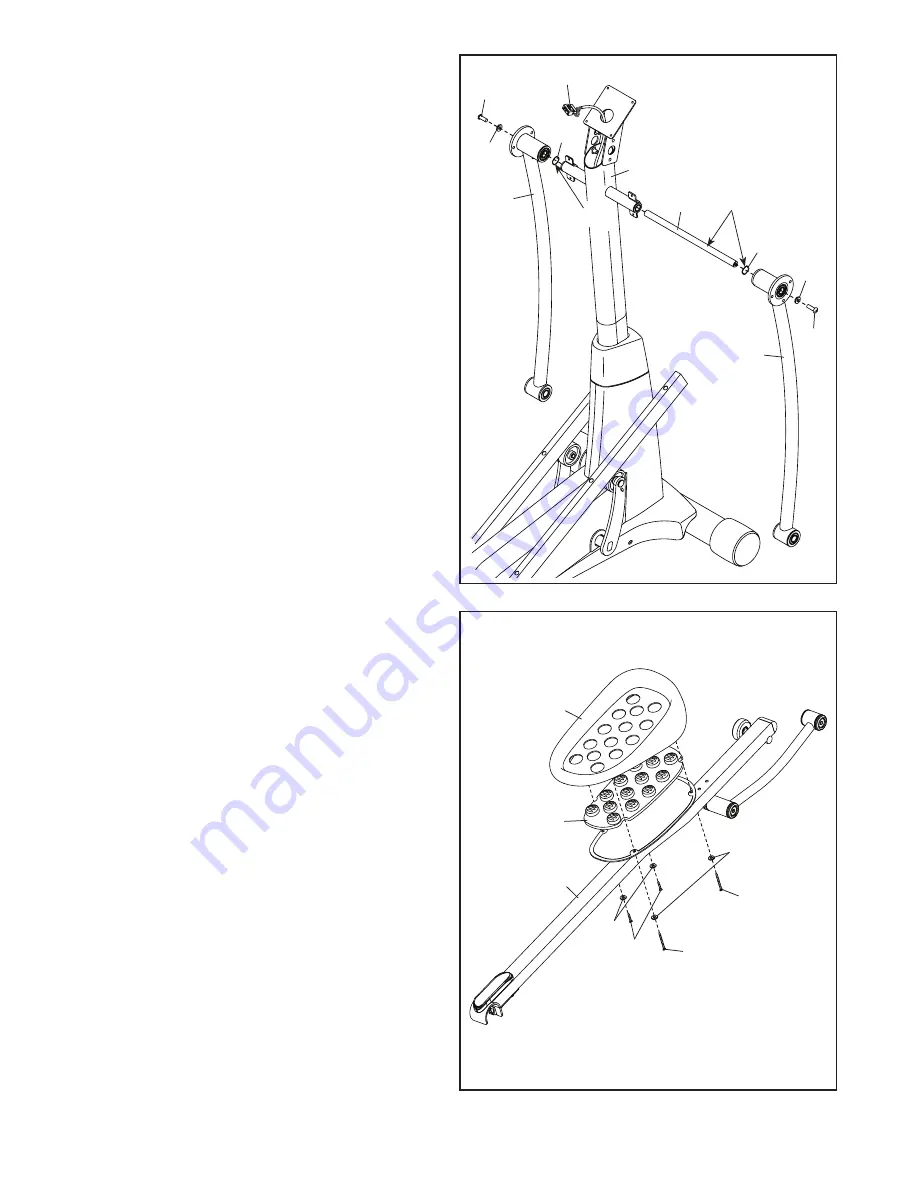
6.  Identify the Right Pedal (14), the Right Gel Pad 

(158), and the Right Pedal Arm (12) and orient 
them as shown.


Set the Right Gel Pad (158) on the Right Pedal 
Arm (12). Then, set the Right Pedal (14) on the 
Right Gel Pad.


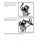
Attach the Right Pedal (14) to the Right Pedal 
Arm (12) with two M6 x 12mm Screws (111) 
and two M6 Washers (112); 

do not tighten the 

Screws yet.


Next, tighten two M6 x 50mm Screws (62) and 
two M6 Washers (112) into the Right Pedal Arm 
(12) and the Right Pedal (14). 

Then, tighten the 

two M6 x 12mm Screws (111). 


Attach the Left Pedal (not shown) to the Left 
Pedal Arm (not shown) assembly in the same 
way.

Summary of Contents for E10 REAR DRIVE NTEVEL89909.2

Page 1: ...ore using this equipment Keep this manual for future reference CUSTOMER SERVICE UNITED KINGDOM Call 08457 089 009 From Ireland 053 92 36102 Website www iconsupport eu E mail csuk iconeurope com Write...

Page 2: ...e replacement decal Apply the decal in the location shown Note The decal s may not be shown at actual size WARNING DECAL PLACEMENT 2 IMPORTANT PRECAUTIONS 3 BEFORE YOU BEGIN 4 PART IDENTIFICATION CHAR...

Page 3: ...g the power cord into a grounded circuit 10 Do not modify the power cord or use an adapter to connect the power cord to an improper receptacle Keep the power cord away from heated surfaces Do not use...

Page 4: ...t cover of this manual To help us assist you note the product model number and serial number before contacting us The model number and the location of the serial number decal are shown on the front co...

Page 5: ...m Screw 111 4 PART IDENTIFICATION CHART Use the drawings below to identify the small parts needed for assembly The number in parentheses below each drawing is the key number of the part from the PART...

Page 6: ...avoid damaging parts do not use power tools ASSEMBLY 1 Go to www iconsupport eu on your computer and register your product activates your warranty saves you time if you ever need to contact Customer...

Page 7: ...p Cover 27 near the Main Frame 1 Locate the wire tie in the Upright 5 Tie the lower end of the wire tie to the Wire Harness 60 Next pull the upper end of the wire tie until the Wire Harness is routed...

Page 8: ...o each end of the Upright Axle 48 at the same time Avoid damaging the Wire Harness 60 Grease Grease 95 5 7 102 95 102 118 48 60 6 118 14 12 111 112 112 62 62 158 6 Identify the Right Pedal 14 the Righ...

Page 9: ...Repeat this step on the other side of the elliptical 32 12 130 7 Apply grease to the axle on the right Crank Arm 39 Orient a Pedal Arm Sleeve 46 so that the flat side is facing the elliptical Slide th...

Page 10: ...sing a second hex key tighten another M8 x 35mm Screw 149 a Small Axle Cover 56 and an M8 Washer 95 into the other end of the Link Arm Axle 114 Tip Avoid damaging the Small Axle Cover when tightening...

Page 11: ...ight and Left Frame Covers 21 22 12 Identify the Right Handlebar 10 and orient it as shown Have a second person hold the Right Handlebar 10 near the right side of the Upright 5 Insert the Pulse Wire 1...

Page 12: ...o M4 x 19mm Screws 156 through the Upright 5 into the upper end of the Console 33 Make sure to start the Screws into the indicated upper holes in the Console Do not tighten the M4 x 19mm Screws 156 ye...

Page 13: ...25 16 Orient the Front Upright Cover 24 as shown Attach the Front Upright Cover 24 around the Upright 5 by pressing the tabs on the Front Upright Cover into the Rear Upright Cover 25 15 Attach the low...

Page 14: ...in the power cord 1 Plug the indicated end of the power cord into the socket on the frame 2 Plug the power cord into an appropriate outlet that is properly installed and earthed in accordance with all...

Page 15: ...ull the magnets on the pedal arms off the han dlebars Then lift the latches under the pedal arms and set the pedal arms on the sleeves on the crank arms Release the latches and make sure that the peda...

Page 16: ...smount the elliptical wait until the pedals come to a complete stop Note The elliptical does not have a free wheel the pedals will continue to move until the flywheel stops When the pedals are station...

Page 17: ...s the iFit interactive workout system which enables the console to accept iFit cards containing workouts designed to help you achieve specific fitness goals For example lose unwanted pounds with the 8...

Page 18: ...e you turn on the console the manual mode will be selected If you have selected a workout reselect the manual mode by pressing any of the Workouts buttons repeatedly until zeros appear in the display...

Page 19: ...sheets of plastic on the metal contacts on the handgrip heart rate moni tor remove the plastic To mea sure your heart rate hold the handgrip heart rate monitor with your palms resting against the met...

Page 20: ...he next segment of the profile will begin to flash If a different resis tance level and or target speed is programmed for the next segment the resistance level and or target speed will appear in the d...

Page 21: ...decrease buttons next to the iFit slot A moment after you select a workout the voice of a personal trainer will begin guiding you through your workout iFit workouts function in the same way as preset...

Page 22: ...backlight option Press the Resistance increase button repeatedly to select the desired backlight option The lower left display will show the total number of hours that the console has been used since...

Page 23: ...calibrates When the ramp stops moving the ramp is calibrated Then at the same time press the Resistance increase and decrease buttons repeatedly to exit the calibration mode HOW TO ADJUST THE REED SWI...

Page 24: ...he Left Pedal Arm off the left Pedal Arm Sleeve 46 Then remove the M4 x 16mm Round Head Screws 152 the M4 x 42mm Screws 153 and the M4 x 25mm Screw 162 from the Right and Left Shields 18 19 Note Not a...

Page 25: ...c Exercise If your goal is to strengthen your cardiovascular system you must perform aerobic exercise which is activity that requires large amounts of oxygen for prolonged periods of time For aerobic...

Page 26: ...lles Stretch With one leg in front of the other reach forward and place your hands against a wall Keep your back leg straight and your back foot flat on the floor Bend your front leg lean forward and...

Page 27: ...ght Axle 49 2 Latch Housing 50 2 Latch 51 2 Large Latch Spring 52 2 Latch Insert 53 4 Long Latch Spring 54 16 Arm Leg Bushing 55 4 M4 x 16mm Flat Head Screw 56 6 Small Axle Cover 57 2 Upright Bushing...

Page 28: ...1 Control Box 125 1 Transformer 126 2 M10 Locknut 127 2 Long C pin 128 2 Short C pin 129 2 M4 x 12mm Screw 130 1 Ramp 131 1 Ramp Cover 132 4 Ramp Bushing 133 1 Ramp Axle 134 1 Lift Motor 135 1 Motor W...

Page 29: ...121 95 113 58 47 46 32 101 32 101 121 95 113 47 46 58 54 54 127 106 49 51 52 50 53 128 43 149 114 56 95 114 56 54 54 54 56 5 24 109 95 56 27 28 13 112 111 62 30 31 31 28 30 111 12 62 112 31 31 62 111...

Page 30: ...08 110 72 39 86 100 119 147 107 38 61 115 116 2 37 4 37 122 39 107 1 64 41 16 100 36 36 126 3 126 16 134 41 41 64 60 148 135 145 107 133 131 130 29 29 29 29 29 85 132 132 132 108 40 137 45 141 139 136...

Page 31: ...31 17 17 21 29 29 29 29 29 20 152 153 162 152 152 19 153 18 153 153 22 152 152 152 152 152 152 152 23 EXPLODED DRAWING C Model No NTEVEL89909 2 R0114A...

Page 32: ...the EXPLODED DRAWING near the end of this manual ORDERING REPLACEMENT PARTS This electronic product must not be disposed of in municipal waste To preserve the environment this product must be recycled...

Reviews: