background image

19

HOW TO USE A PRESET PROGRAM

1. Turn on the console.

See step 1 on page 16.

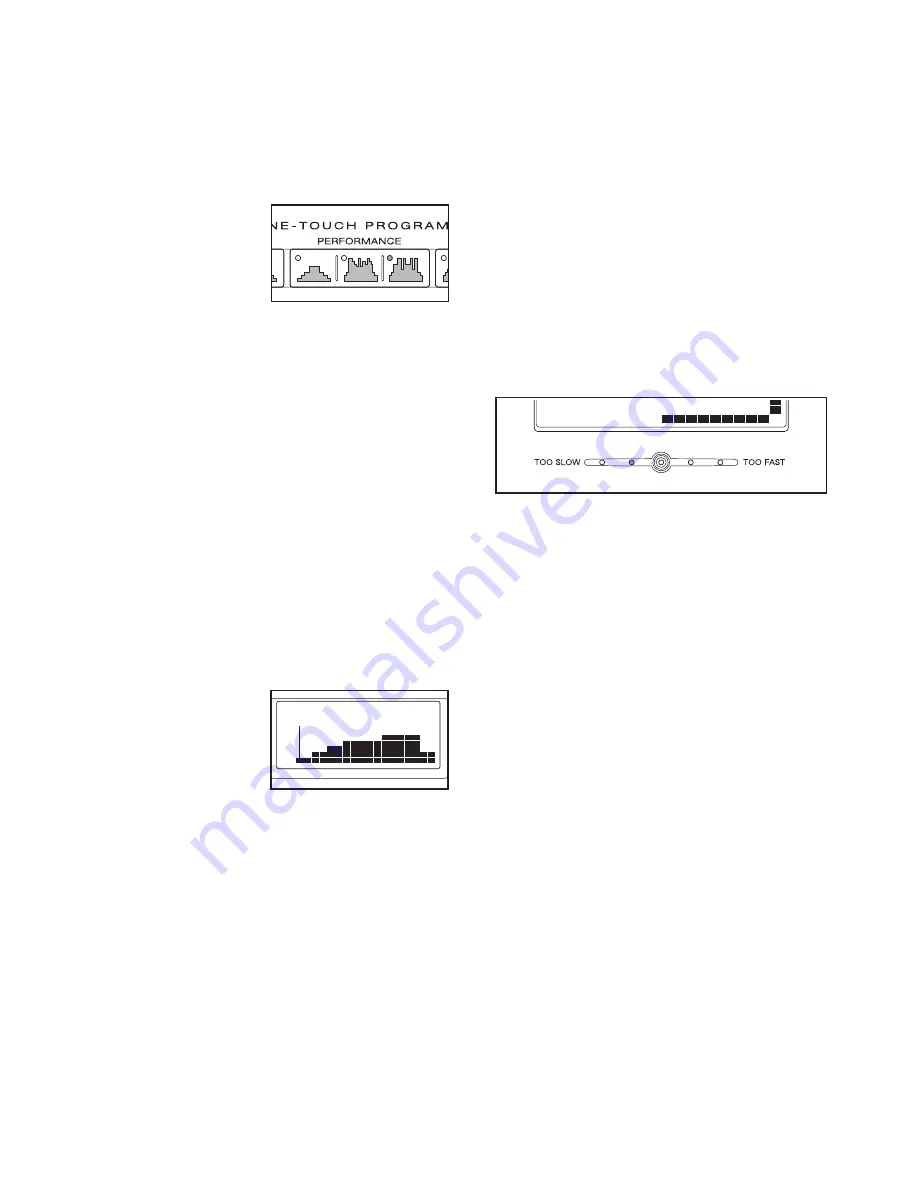
2. Select a preset program.

To select a preset

program, press one

of the Aerobic,

Performance, or

Endurance buttons.

When an Aerobic,

Performance, or

Endurance button is pressed, the indicator on the

button will light. When a preset program is se-

lected, a profile of the first several resistance set-

tings of the program will appear in the matrix, the

program time will appear in the Time display, the

maximum resistance setting of the program will

flash in the Resistance display, and the maximum

speed setting of the program will flash in the Speed

display for a few seconds.

3. Press the Start button or begin pedaling to

start the program.

Each program is divided into either 20 or 30 one-

minute segments. One resistance setting and one

pace setting are programmed for each segment.

Note: The same resistance setting and/or target

pace may be programmed for two or more consec-

utive segments.

When you start the

program, the resis-

tance setting for the

first segment will be

shown in the flash-

ing Current

Segment column of

the matrix. The resistance settings for the next sev-

eral segments will be shown in the columns to the

right.

When only three seconds remain in the first seg-

ment of the program, both the Current Segment

column and the column to the right will flash, a se-

ries of tones will sound, and the time will flash in

the Time display. When the first segment ends,

all

resistance settings will move one column to the

left.

The resistance setting for the second segment

will then be shown in the flashing Current Segment

column and the resistance of the pedals will auto-

matically change to the resistance setting for the

second segment.

The program will continue until no time remains in

the Time display.

4. Use the pace guide to pace your exercise.

Throughout the program, the pace guide will

prompt you to increase or decrease your pedaling

pace. When one of the “Too Slow” indicators lights,

increase your pace; when one of the “Too Fast” in-

dicators lights, decrease your pace. When the cen-

ter indicator lights, maintain your current pace.

IMPORTANT: The pace guide is intended only

to provide a goal. Make sure to pedal at a pace

that is comfortable for you.

If you stop pedaling for several seconds, a tone will

sound and the program will pause. To restart the

program, simply resume pedaling.

5. Monitor your progress with the displays.

See step 5 on page 16.

6. Measure your heart rate if desired.

See step 6 on page 17.

7. When you are finished exercising, the console

will automatically turn off.

See step 7 on page 17.

Current Segment

Summary of Contents for Elite 1300 Elliptical

Page 1: ...CONTACT THE STORE please contact Customer Care IMPORTANT You must note the product model number and serial number see the drawing above before contacting us CALL TOLL FREE 1 888 825 2588 Mon Fri 6 a m...

Page 2: ...BLESHOOTING 22 EXERCISE GUIDELINES 23 PART LIST 24 EXPLODED DRAWING 25 ORDERING REPLACEMENT PARTS Back Cover LIMITED WARRANTY Back Cover WARNING DECAL PLACEMENT The warning decal shown here has been a...

Page 3: ...5 Inspect and properly tighten all parts regu larly Replace any worn parts immediately 6 Keep children under age 12 and pets away from your elliptical exerciser at all times 7 Your elliptical exercise...

Page 4: ...r benefit read this manual carefully before you use the elliptical exerciser If you have ques tions after reading this manual please see the front cover of this manual To help us assist you note the p...

Page 5: ...LIST near the end of this manual The number following the parentheses is the quantity needed for assembly Note Some small parts may have been pre assembled If a part is not in the hardware kit check...

Page 6: ...ght 2 in the position shown Connect the Upper Wire Harness 77 to the Lower Wire Harness 78 Attach the Upright 2 to the Frame 1 with four M10 x 25mm Patch Screws 48 and four M10 Split Washers 85 Make s...

Page 7: ...two Wave Washers 88 and two Thrust Washers 66 Slide a Weld Spacer 89 onto the Left Crank Arm 83 Next identify the Left Track Arm 12 which is marked with an L Orient the Left Track Arm as shown and sl...

Page 8: ...Leg not shown in the same way 5 21 67 67 85 85 54 54 14 6 Apply a thin film of grease to the barrel of an M10 x 65mm Bolt Set 94 Next fit the bracket on the Left Pedal Leg 14 onto the bracket on the L...

Page 9: ...ase to the sides of two Wave Washers 88 and two Thrust Washers 66 Slide the Left Handlebar 19 onto the Handlebar Axle 16 as shown Next slide a Wave Washer 88 onto the end of the Handlebar Axle Slide a...

Page 10: ...tighten the Bolt Set the left Handlebar Leg must be able to pivot freely Attach the right Handlebar Leg not shown to the Right Pedal Leg not shown in the same way See step 7 Tighten the four M8 x 38mm...

Page 11: ...m Screws 57 See step 10 Tighten the six M4 x 16mm Screws 47 11 2 26 57 12 Make sure that all parts of the elliptical exerciser are properly tightened Cover the floor beneath the el liptical exerciser...

Page 12: ...steps below Make sure that the chest pulse sensor is worn ex actly as described at the left If the chest pulse sen sor does not function when positioned as described move it slightly lower or higher...

Page 13: ...st pulse sensor after each use The chest pulse sensor is activated when the electrode areas are wetted and the chest pulse sen sor is put on the chest pulse sensor shuts off when it is removed and the...

Page 14: ...he elliptical exerciser rocks slightly on your floor see the inset drawings and turn the leveling feet under the front and rear of the elliptical exerciser until the rocking motion is eliminated EXERC...

Page 15: ...the console will display feedback until the goal is reached In addition the console offers nine preset programs Each program automatically changes the resistance of the pedals and prompts you to incr...

Page 16: ...page 20 4 Begin pedaling and change the resistance of the pedals as desired As you pedal change the resistance of the pedals by pressing the One touch Resistance buttons if desired Note After the One...

Page 17: ...below Note If you wear the chest pulse sensor and hold the handgrip pulse sensor at the same time the console will not display your heart rate accurately If there are sheets of clear plastic on the me...

Page 18: ...gment of the program ends a se ries of tones will sound and the current resistance setting and the current pace setting will be saved in memory The columns of indicators will then move one column to t...

Page 19: ...When only three seconds remain in the first seg ment of the program both the Current Segment column and the column to the right will flash a se ries of tones will sound and the time will flash in the...

Page 20: ...the chest pulse sensor or use the handgrip pulse sen sor If you use the handgrip pulse sensor it is not necessary to hold the handgrips continuously dur ing the program however you should hold the han...

Page 21: ...urrent pace IMPORTANT The target heart rate settings are intended only to provide motivation Make sure to exercise at a pace that is comfortable for you Note During the program you can manually over r...

Page 22: ...side shield loosen the side shield mounting screws and move the side shield slightly until the pedal disc stops rubbing Then retighten the side shield mounting screws 4 SYMPTOM THE PEDAL WHEELS SQUEAK...

Page 23: ...goal is to strengthen your cardiovascular system you must perform aerobic exer cise which is activity that requires large amounts of oxygen for prolonged periods of time For aerobic ex ercise adjust t...

Page 24: ...Button Screw 55 4 7mm Spacer 56 4 M8 x 19mm Button Screw 57 2 M4 x 19mm Screw 58 4 M8 x 38mm Button Bolt 59 20 M5 x 16mm Screw 60 4 16mm Spacer 61 2 M8 x 48mm Bolt 62 2 3mm Spacer 63 8 Pedal Bushing 6...

Page 25: ...68 71 3 3 24 40 40 40 24 4 47 57 2 47 47 47 47 33 33 85 48 85 85 50 46 46 22 72 46 22 46 50 40 36 24 24 24 8 24 42 16 45 45 47 87 43 38 27 29 52 27 27 27 35 35 35 34 52 52 52 47 95 72 70 70 37 37 96 9...

Page 26: ...26 49 5 59 59 59 59 7 64 73 6 59 59 59 59 5 49 64 53 53 EXPLODED DRAWING B Model No NTEL4255 3 R0509A...

Page 27: ...1 60 91 91 91 62 60 41 56 66 42 41 56 66 58 61 28 65 72 63 63 63 41 56 66 41 56 66 44 67 67 54 54 67 54 54 34 34 34 34 34 34 34 34 55 55 55 55 88 72 72 88 88 88 89 89 89 90 90 91 91 90 90 91 91 72 72...

Page 28: ...ntial damages arising out of or in con nection with the use or performance of the product or damages with respect to any economic loss loss of property loss of revenues or profits loss of enjoyment or...

Reviews: