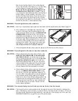
background image

13

OPERATION AND ADJUSTMENT

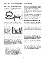
THE PRE-LUBRICATED WALKING BELT

Your treadmill features a walking belt coated with high-
performance lubricant. 

IMPORTANT: Never apply sil-

icone spray or other substances to the walking
belt or the walking platform. Such substances will
deteriorate the walking belt and cause excessive
wear.

HOW TO PLUG IN THE POWER CORD 

Your treadmill, like any other type of sophisticated
electronic equipment, can be seriously damaged by
sudden voltage changes in your home’s power.
Voltage surges, spikes, and noise interference can 
result from weather conditions or from other appliances
being turned on or off. 

To decrease the possibility of

your treadmill being damaged, always use a surge
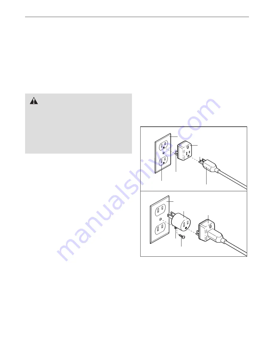
suppressor with your treadmill (see drawing 1 at
the right). To purchase a surge suppressor, see
your local NORDICTRACK dealer or call the tele-
phone number on the front cover of this manual
and order part number 146148, or see your local
electronics store.

Use only a single-outlet surge suppressor that is
UL 1449 listed as a transient voltage surge sup-
pressor (TVSS). The surge suppressor must have a
UL suppressed voltage rating of 400 volts or less
and a minimum surge dissipation of 450 joules.
The surge suppressor must be electrically rated for
120 volts AC and 15 amps. There must be a moni-
toring light on the surge suppressor to indicate
whether it is functioning properly. Failure to use a
properly functioning surge suppressor could result
in damage to the control system of the treadmill. If
the control system is damaged, the walking belt
may change speed, accelerate, or stop unexpect-
edly, which may result in a fall and serious injury.

This product must be grounded. 

If it should malfunc-

tion or break down, grounding provides a path of least
resistance for electric current to reduce the risk of elec-

tric shock. This product is equipped with a cord having
an equipment-grounding conductor and a grounding
plug. 

Plug the power cord into a surge suppressor,

and plug the surge suppressor into an appropriate
outlet that is properly installed and grounded in
accordance with all local codes and ordinances.
Important: The treadmill is not compatible with
GFCI-equipped outlets.

This product is for use on a nominal 120-volt circuit,
and has a grounding plug that looks like the plug illus-
trated in drawing 1 below. A temporary adapter that
looks like the adapter illustrated in drawing 2 may be
used to connect the surge suppressor to a 2-pole 
receptacle as shown in drawing 2 if a properly 
grounded outlet is not available. 

The temporary adapter should be used only until a
properly grounded outlet (drawing 1) can be installed
by a qualified electrician. 

The green-colored rigid ear, lug, or the like extending
from the adapter must be connected to a permanent
ground such as a properly grounded outlet box cover.
Whenever the adapter is used it must be held in place
by a metal screw. 

Some 2-pole receptacle outlet box

covers are not grounded. Contact a qualified elec-
trician to determine if the outlet box cover is
grounded before using an adapter.

DANGER:

Improper connection

of the equipment-grounding conductor can
result in an increased risk of electric shock.
Check with a qualified electrician or service-
man if you are in doubt as to whether the
product is properly grounded. Do not modify
the plug provided with the product—if it will
not fit the outlet, have a proper outlet 
installed by a qualified electrician.

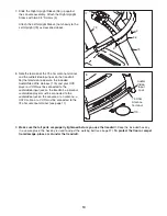
1

2

Grounded Outlet Box

Grounded Outlet Box

Grounding Plug

Surge Suppressor

Surge Suppressor

Grounding Pin

Adapter

Lug

Metal Screw

Grounded Outlet

Grounding Pin

Summary of Contents for Elite 4200 Treadmill

Page 1: ...we are com mitted to providing complete cus tomer satisfaction If you have questions or if parts are missing PLEASE DO NOT CONTACT THE STORE please contact Customer Care IMPORTANT You must note the p...

Page 2: ...T PARTS Back Cover LIMITED WARRANTY Back Cover Note An EXPLODED DRAWING is attached in the center of this manual 2 The decals shown here have been applied in the locations shown If a decal is missing...

Page 3: ...extension cord 12 Use only a single outlet surge suppressor that meets all of the specifications described on page 13 To purchase a surge suppressor see your local NORDICTRACK dealer or call the tele...

Page 4: ...respect to proper grounding of the mast and supporting struc ture grounding of the lead in wire to an an tenna discharge unit size of grounding con ductors location of antenna discharge unit connecti...

Page 5: ...nd Wire Ground Wire Antenna Discharge Unit To External Antenna Terminal of Treadmill Mast Service Entrance Equipment Power Service Grounding Electrode System e g Interior Metal Water Pipe Service Entr...

Page 6: ...e treadmill If you have questions after read ing this manual please see the front cover of this man ual To help us assist you note the product model number and serial number before contacting us The m...

Page 7: ...is the key number of the part from the PART LIST near the end of this manual The number after the parentheses is the quantity needed for assembly Note If a part is not in the parts bag check to see i...

Page 8: ...It may be necessary to tip the tops of the Uprights forward slightly as you thread the Upright Bolts 72 into the Uprights Hold Left Upright 73 near the Left Base Cover 76 and insert the TV Cable 49 an...

Page 9: ...Console Assembly 4 75 74 5 Connect the TV Cable 49 and the AV Wire 97 to the cables extending from the console assem bly Then insert the connectors down into the Uprights 73 74 Next insert the bracket...

Page 10: ...ust be connected to the 75 ohm antenna terminal see page 11 8 9 Make sure that all parts are properly tightened before you use the treadmill Keep the included hex key in a secure place the hex key is...

Page 11: ...V cable to the video output jack on your VCR 2 Plug in the power cord of your VCR See your VCR user s manual for proper grounding instructions 3 Connect the 75 ohm CATV cable to the 75 ohm an tenna te...

Page 12: ...sture Do not expose the chest pulse sensor to direct sunlight for extended periods of time do not expose it to temperatures above 122 F 50 C or below 14 F 10 C Do not excessively bend or stretch the s...

Page 13: ...func tion or break down grounding provides a path of least resistance for electric current to reduce the risk of elec tric shock This product is equipped with a cord having an equipment grounding cond...

Page 14: ...controls the speed and incline of the treadmill as it guides you through an effective workout You can even create your own cus tom programs and save them for future use The console also offers four he...

Page 15: ...or kilometers To find out which unit of measurement is selected or to change the unit of mea surement see THE INFORMATION MODE on page 23 For simplicity all instructions in this section refer to mile...

Page 16: ...while you watch the television Press the Display button repeatedly to select the desired dis play mode To reset the console press the Stop button re move the key and then reinsert the key Measure you...

Page 17: ...he walking belt or the incline of the treadmill at any time during the program press the Speed or Incline buttons During an event training program the screen will show the number of kilometers or mile...

Page 18: ...ine setting may be pro grammed for two or more consecutive segments When only three seconds remain in the first seg ment of the program a series of tones will sound If the speed and or the incline of...

Page 19: ...eed setting and an incline setting for the first segment simply adjust the speed and in cline of the treadmill as desired by pressing the Speed and Incline buttons When the first segment of the progra...

Page 20: ...am see step 4 on page 18 If desired you can redesign the program while using it To change the speed setting or the in cline setting for the current segment simply press the Speed or Incline buttons Wh...

Page 21: ...and begin walking Heart rate program 1 is divided into one minute segments The same target heart rate setting is programmed for all segments except for the first two segments Heart rate programs 2 3 a...

Page 22: ...not wish to use the television select the Console mode Press the Channel buttons to select the desired channel When the television is turned on the screen will show the last channel that was selected...

Page 23: ...e TV button is pressed the brightness level indicator will appear on the television screen Press the Volume VOL buttons to adjust the brightness setting if desired Next press the Channel CHAN buttons...

Page 24: ...nd slide the platform cushions toward the front of the treadmill To decrease the firmness step off the treadmill and slide the platform cushions toward the back of the treadmill Note Make sure that bo...

Page 25: ...readmill convert the treadmill to the stor age position as described above Make sure that the latch knob is locked in the storage position 1 Hold the handrails and place one foot against a wheel 2 Til...

Page 26: ...pped To reset the circuit breaker wait for five minutes and then press the switch to the reset position PROBLEM The power turns off during use SOLUTION a Check the reset off circuit breaker see the dr...

Page 27: ...manual PROBLEM The walking belt is off center or slips when walked on SOLUTION a If the walking belt is off center remove the key and UNPLUG THE POWER CORD If the walking belt has shifted to the left...

Page 28: ...and the other is reflected from tall buildings hills or other objects Change the direction or posi tion of the antenna to improve reception Blue Screen If the treadmill is located in the fringe area...

Page 29: ...your goal is to strengthen your cardiovascular system you must perform aerobic exer cise which is activity that requires large amounts of oxygen for prolonged periods of time For aerobic ex ercise adj...

Page 30: ...1 Lift Motor Bolt Top 41 1 AV Cover 42 2 Platform Cushion 43 1 Power Cord Assembly 44 1 Hood 45 4 Hood Clip 46 2 Grommet 47 1 Walking Belt 48 1 Frame 49 1 TV Cable 50 1 Transformer 51 1 Right Rear Foo...

Page 31: ...Fastener 115 1 Audio Video Wire Harness 116 2 Console Clamp 117 1 Upper Latch Bolt 118 1 Latch Knob 119 1 Latch Endcap 120 1 Left Pulse Grip 121 1 Right Pulse Grip 122 2 4 Ground Wire 123 1 Console T...

Page 32: ...17 19 16 15 1 2 2 1 13 29 11 53 38 52 52 24 38 34 4 4 4 4 13 46 29 4 4 4 30 30 25 9 8 61 61 105 56 48 103 106 107 108 4 44 4 4 4 45 45 69 50 98 55 33 55 55 115 100 117 38 113 38 119 118 42 4 128 3 3...

Page 33: ...4 94 75 65 67 75 63 64 90 114 114 4 4 4 4 4 4 82 81 4 4 4 4 4 80 4 49 76 77 4 4 4 4 90 72 90 72 90 41 4 4 4 4 4 4 4 110 4 111 112 102 97 97 49 116 116 80 4 4 4 4 4 4 4 120 121 66 4 4 4 71 122 84 123...

Page 34: ...ce center will be the customer s responsibility This warranty does not extend to any product or damage to a product caused by or attributable to freight damage abuse misuse improper or abnormal usage...

Reviews: