background image

27

 Key No.  Qty. 

Description

 Key No.  Qty. 

Description

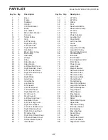
PART LIST

Model No. NTEVEL17018.0 R1218A

 1  1  Base

 2  1  Frame

 3  1  Stabilizer

 4  1  Upright

  5 

Console Bracket

 6  1  Brace

  7 

Drive Belt A

  8 

M8 x 38mm Washer

 9  1  Console

  10 

Tablet Holder

 11  2  Grip

  12 

Left Pivot Leg

  13 

Right Pivot Leg

  14 

Left Pedal Arm

  15 

Right Pedal Arm

 16  2  Handlebar

  17 

M5 x 10mm Screw

  18 

Belt Clamp

  19 

Glide Belt

 20  4  Wedge

 21  2  Strap

  22 

Strap Bracket

  23 

Strap Clamp

  24 

Left Rear Belt Cover

  25 

Right Rear Belt Cover

  26 

Left Front Belt Cover

  27 

Right Front Belt Cover

  28 

Left Pedal

  29 

Right Pedal

  30 

Axle Cover

  31 

Axle Washer

  32 

Leg Bearing

  33 

Flex Spacer

  34 

Left Pivot Spacer

  35 

Left Shield Cover

  36 

Right Shield Cover

  37 

Pivot Cover A

  38 

Pivot Cover B

  39 

Left Rear Leg Cover

  40 

Handlebar Cover

  41 

Left Front Leg Cover

  42 

Right Pivot Spacer

  43 

Left Front Shield Cover

  44 

Right Rear Leg Cover

  45 

Right Front Leg Cover

  46 

Pivot Bushing

  47 

Right Front Shield Cover

  48 

Console Bracket Cover

  49 

Accelerometer Sensor

  50 

Idler Spacer

  51 

40" Wire

  52 

48" Wire

 53  2  Wheel

 54  2  Foot

  55 

Reed Switch/Wire

  56 

Reed Switch Clamp

  57 

27" Wire

  58 

38" Wire

  59 

Power Adapter

  60 

Leveling Foot

  61 

Drive Belt B

  62 

Left Inner Disc

 63  1  Crank

 64  1  Flywheel

  65 

Large Crank Pulley

  66 

Large Idler Pulley

  67 

Crank Pulley Bracket

  68 

Crank Bracket

  69 

Idler Hub

  70 

Idler Bracket

  71 

Idler Adjustment Bolt

  72 

Pivot Brace

  73 

Power Cover

  74 

Lower Axle

  75 

Magnet Bracket

  76 

Resistance Motor

  77 

Resistance Rod

  78 

Resistance Disc

  79 

Resistance Block

  80 

Crank Washer

  81 

Crank Bearing

  82 

Small Crank Spacer

  83 

Large Crank Spacer

  84 

Small Weld Spacer

  85 

Large Spacer

  86 

Roller Spacer

  87 

Flex Spacer

  88 

Roller Bearing

 89  2  Roller

  90 

Roller Weld Spacer

  91 

Upper Axle

  92 

Small Idler Pulley

  93 

Idler Flex Spacer

  94 

Idler Bearing

  95 

Brace Bushing

  96 

Accent Ring

  97 

Shield Disc

  98 

Left Outer Shield

  99 

Left Inner Shield

  100 

Right Outer Shield

Summary of Contents for Freestride Trainer F55i

Page 1: ...p this manual for future reference Serial Number Decal CUSTOMER SERVICE UNITED KINGDOM Call 0330 123 1045 From Ireland 053 92 36102 Website iconsupport eu E mail csuk iconeurope com Write ICON Health...

Page 2: ...E THE ELLIPTICAL 13 MAINTENANCE AND TROUBLESHOOTING 22 EXERCISE GUIDELINES 24 PART LIST 27 EXPLODED DRAWING 29 ORDERING REPLACEMENT PARTS Back Cover RECYCLING INFORMATION Back Cover 383106 NORDICTRACK...

Page 3: ...e and dust Do not put the elliptical in a garage or covered patio or near water 7 Place the elliptical on a level surface with at least 4 ft 1 2 m of clearance in the front of the elliptical 6 ft 1 8...

Page 4: ...after reading this manual please see the front cover of this manual To help us assist you note the product model number and serial number before contacting us The model number and the location of the...

Page 5: ...ing the key number is the quantity needed for assembly Note If a part is not in the hardware kit check to see if it has been preassembled Extra parts may be included M8 x 14mm Shoulder Screw 122 2 M4...

Page 6: ...embly may be easier if you have a set of wrenches To avoid damaging parts do not use power tools ASSEMBLY 1 1 To register your product and activate your warranty in the UK go to iconsupport eu If you...

Page 7: ...Avoid pinching the wires With the help of one or two other people set the Upright 4 on the pins A on the Frame 2 Attach the Upright 4 to the Frame 2 with eight M10 x 25mm Screws 123 start all the Scre...

Page 8: ...35 36 47 143 43 4 Avoid pinching the wires 12 14 15 13 31 30 122 Grease 5 5 Identify the Right Pedal Arm 15 Using a plastic bag to keep your fingers clean apply a generous amount of the included greas...

Page 9: ...while you perform the following action Make sure to orient the Strap Clamp 23 as shown in the inset drawing Attach the Strap 21 to the Strap Bracket 22 on the Right Pedal Arm 15 with three M6 x 20mm...

Page 10: ...right 4 and attach it with two M10 x 45mm Bolts 119 and two M10 x 18mm Washers 138 Tip Avoid pinching the wires Press the Right Rear Leg Cover 44 into the Pivot Covers A and B 37 38 Then press the Han...

Page 11: ...a second person hold the Console 9 near the Console Bracket 5 and insert the Wires B on the Console through the hole in the Console Bracket as shown Tip Avoid pinching the wires Attach the Console 9...

Page 12: ...48 to the Accessory Tray 111 with two M4 x 16mm Screws 143 Avoid pinching the wires 111 10 142 143 9 15 59 15 Plug the Power Adapter 59 into the receptacle on the frame of the elliptical Then plug th...

Page 13: ...the power adapter A into the receptacle on the frame of the exercise bike Then plug the power adapter into an appropri ate outlet that is properly installed in accordance with all local codes and ordi...

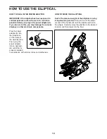
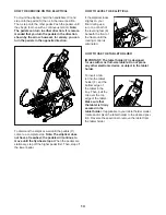
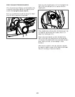
Page 14: ...ationary step off the higher pedal first Then step off the lower pedal HOW TO LEVEL THE ELLIPTICAL If the elliptical rocks slightly on your floor during use turn one or both of the leveling feet E ben...

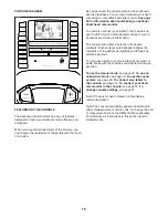
Page 15: ...a selection of onboard workouts Each workout automatically changes the resistance of the pedals as it guides you through an effective workout You can even listen to your favorite workout music or audi...

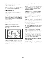
Page 16: ...stance This display will show the distance that you have pedaled in miles mi or kilometers km To change the unit of measurement press the St Met button repeatedly Pulse BPM This display will show your...

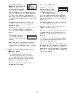
Page 17: ...nforma tion about the optional heart rate monitor see page 20 Note The console is compatible with Bluetooth Smart heart rate monitors When your heartbeat is detected your heart rate will be shown in t...

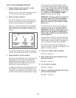
Page 18: ...edaling speed near the target speed for the current segment When the words GO FASTER appear in the display increase your pace When the words SLOW DOWN appear decrease your pace When the words IN RANGE...

Page 19: ...the console will turn solid blue 4 Record and track your workout information Follow the instructions in the iFit Smart Cardio Equipment app to record and track your workout information 5 Disconnect y...

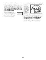
Page 20: ...sing the volume increase and decrease buttons on the console or the volume control on your personal audio player THE OPTIONAL CHEST HEART RATE MONITOR Whether your goal is to burn fat or to strengthen...

Page 21: ...in the display To change the unit of measurement press the Enter button or the St Met button repeatedly To view workout information in standard units select ENGLISH To view workout information in met...

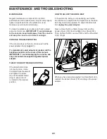
Page 22: ...MPORTANT To avoid damaging the console use only a manufacturer supplied regulated power adapter TABLET HOLDER TROUBLESHOOTING If the tablet holder does not stay in place rotate the tablet holder backw...

Page 23: ...gnet 113 is aligned with the Reed Switch Then slightly loosen the two M4 x 25mm Screws 153 and slide the Reed Switch 55 slightly closer to or away from the Magnet 113 Plug in the power adapter and roc...

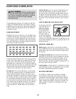
Page 24: ...m aerobic exercise which is activity that requires large amounts of oxygen for prolonged periods of time For aerobic exercise adjust the intensity of your exercise until your heart rate is near the hi...

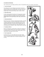
Page 25: ...lles Stretch With one leg in front of the other reach forward and place your hands against a wall Keep your back leg straight and your back foot flat on the floor Bend your front leg lean forward and...

Page 26: ...26 NOTES...
Page 27: ...Leg Cover 45 1 Right Front Leg Cover 46 4 Pivot Bushing 47 1 Right Front Shield Cover 48 1 Console Bracket Cover 49 1 Accelerometer Sensor 50 1 Idler Spacer 51 1 40 Wire 52 1 48 Wire 53 2 Wheel 54 2 F...

Page 28: ...132 1 M10 x 65mm Bolt 133 8 M10 Locknut 134 4 M8 x 13mm Screw 135 1 M6 x 10mm Screw 136 2 M5 Locknut 137 3 M10 Washer 138 4 M10 x 18mm Washer 139 5 M6 Washer 140 11 Clip 141 61 M4 x 16mm Self tapping...

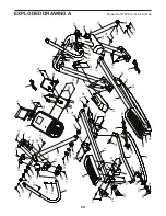
Page 29: ...2 25 22 22 24 27 29 31 31 34 36 38 39 33 35 37 40 40 41 37 43 42 38 44 47 49 51 117 117 11 25 24 27 19 21 122 122 122 142 142 144 121 143 143 143 143 143 151 143 143 141 141 141 141 141 141 151 123 12...

Page 30: ...129 129 129 129 139 139 139 139 159 153 131 8 61 63 66 68 65 7 64 67 69 70 71 80 81 81 81 81 83 86 88 88 85 82 84 87 89 90 92 94 94 93 50 158 158 128 122 128 31 122 132 149 149 133 137 133 134 128 15...

Page 31: ...106 106 62 107 108 110 112 114 115 116 109 111 113 113 141 141 141 141 141 141 141 141 141 141 141 141 141 141 141 141 143 143 148 148 141 143 143 143 147 143 147 141 147 143 141 143 143 148 148 141 1...

Page 32: ...T and the EXPLODED DRAWING near the end of this manual ORDERING REPLACEMENT PARTS This electronic product must not be disposed of in municipal waste To preserve the environment this product must be re...

Reviews: