background image

15

HOW TO USE THE MANUAL MODE

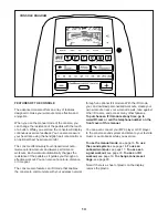
1.   Begin pedaling or press any button on the 

console to turn on the console.

   When you turn on the console, the display will turn 

on. The console will then be ready for use.

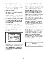
2.  Select the manual mode.

   Press the Manual Control button on the console to 

select the manual mode. 

   If a wireless iFit module is not inserted into the con-

sole and connected to iFit, the manual mode will be 

selected automatically.

3.  Change the resistance of the pedals as desired.

   As you pedal, change the resistance of the pedals 

by pressing the One Touch Resistance increase 

and decrease buttons.

   Note: After you press a button, it will take a 

moment for the pedals to reach the selected resis-

tance level. 

4.  Follow your progress with the display.

   The display can show the following workout 

information:


Calories (Cals.)

—This display mode will show the 

approximate number of calories you have burned.


Calories per Hour (Cals./Hr)

—This display mode 

will show the approximate number of calories you 

are burning per hour.


Distance (Dist.)

—This display mode will show 

the distance that you have pedaled in miles or 

kilometers. 


Pulse

—This display mode will show your heart rate 

when you use the handgrip heart rate monitor or an 

optional chest heart rate monitor (see step 5).


 Resistance  (Resist.)

—This display mode will 

show the resistance level of the pedals for a few 

seconds each time the resistance level changes. 


Speed

—This display mode will show your pedaling 

speed in miles per hour or kilometers per hour.


Time

—When the manual mode is selected, this 

display mode will show the elapsed time. When a 

workout is selected, this display mode will show the 

time remaining in the workout.

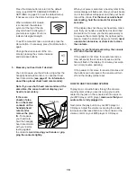
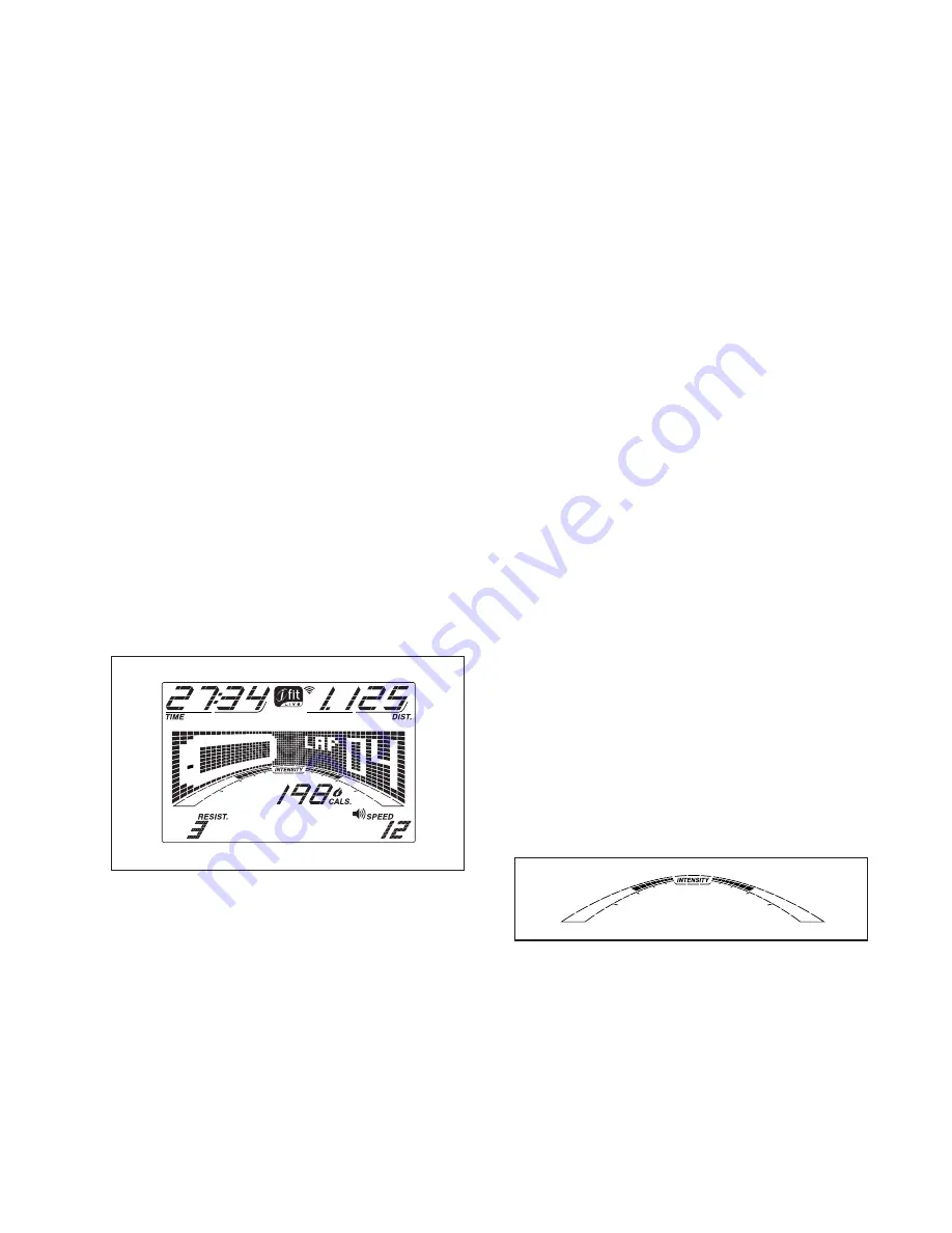
   The matrix offers several display tabs. Press the 

Display button until the desired tab is shown. You 

can also press the increase and decrease buttons 

next to the Enter button.


Speed

—This tab will show a profile of the speed 

settings of the workout. A new segment will appear 

at the end of each minute.


 My  Trail

—This tab will show a track that represents 

1/4 mile (400 m). As you exercise, the flashing 

rectangle will show your progress. The My Trail tab 

will also show the number of laps you complete. 


Calorie

—This tab will show the approximate 

amount of calories you have burned. The height of 

each segment represents the amount of calories 

burned during that segment.

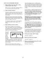
   As you exercise, the workout intensity level bar 

will indicate the approximate intensity level of your 

exercise. 

Summary of Contents for Gxr 4.2

Page 1: ...ual for future reference USER S MANUAL CUSTOMER SERVICE UNITED KINGDOM Call 08457 089 009 From Ireland 053 92 36102 Website www iconsupport eu E mail csuk iconeurope com Write ICON Health Fitness Ltd c o HI Group PLC Express Way CASTLEFORD WF10 5QJ UNITED KINGDOM AUSTRALIA Call 1800 993 770 E mail australiacc iconfitness com Write ICON Health Fitness PO Box 635 WINSTON HILLS NSW 2153 AUSTRALIA www...

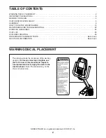
Page 2: ...own Note The decal s may not be shown at actual size NORDICTRACK is a registered trademark of ICON IP Inc TABLE OF CONTENTS WARNING DECAL PLACEMENT 2 IMPORTANT PRECAUTIONS 3 BEFORE YOU BEGIN 4 PART IDENTIFICATION CHART 5 ASSEMBLY 6 HOW TO USE THE EXERCISE BIKE 13 MAINTENANCE AND TROUBLESHOOTING 22 EXERCISE GUIDELINES 24 PART LIST 25 EXPLODED DRAWING 26 ORDERING REPLACEMENT PARTS Back Cover RECYCLI...

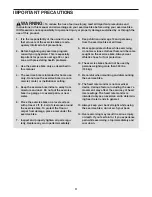
Page 3: ...e the exercise bike on a level surface with at least 2 ft 0 6 m of clearance around the exercise bike To protect the floor or carpet from damage place a mat under the exercise bike 7 Inspect and properly tighten all parts regu larly Replace any worn parts immediately 8 Keep children under age 12 and pets away from the exercise bike at all times 9 Wear appropriate clothes while exercising do not we...

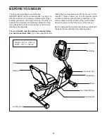
Page 4: ...fully before you use the exercise bike If you have questions after reading this manual please see the front cover of this manual To help us assist you note the product model number and serial number before contacting us The model number and the location of the serial number decal are shown on the front cover of this manual Before reading further please familiarize yourself with the parts that are ...

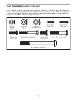
Page 5: ...50 4 PART IDENTIFICATION CHART Use the drawings below to identify the small parts needed for assembly The number in parentheses below each drawing is the key number of the part from the PART LIST near the end of this manual The number following the key number is the quantity needed for assembly Note If a part is not in the hardware kit check to see if it has been preassembled Extra parts may be in...

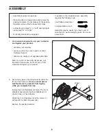
Page 6: ...aterials until you finish all assembly steps Left parts are marked L or Left and right parts are marked R or Right To identify small parts see page 5 In addition to the included tool s assembly requires the following tools one Phillips screwdriver one adjustable wrench Assembly may be easier if you have a set of wrenches To avoid damaging parts do not use power tools ASSEMBLY 62 2 1 2 Wheel 1 Go t...

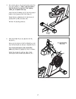
Page 7: ...r Stabilizer 3 to the Frame 1 with two M10 x 95mm Screws 62 Remove the packing material 3 3 62 1 Welded Tubes 4 Slide the Shield Cover 5 upward onto the Upright 4 Have a second person hold the Shield Cover 5 around the Upright 4 until you complete step 5 Tip Avoid pinching the wires inside the Frame 1 Slide the Upright 4 onto the Frame Attach the Upright 4 with five M8 x 16mm Screws 60 and five M8...

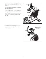
Page 8: ...91 Then pull the other end of the wire tie upward until the Wires 75 76 91 are routed through the Upright 4 Then slide the Shield Cover 5 downward and press it onto the Right and Left Front Shields 21 22 5 76 75 21 4 5 Wire Tie Wire Tie 1 22 6 Tip Avoid pinching the wires Attach the Handlebar 6 to the Upright 4 with four M6 x 20mm Screws 88 and four M6 Split Washers 50 6 6 88 50 4 Avoid pinching t...

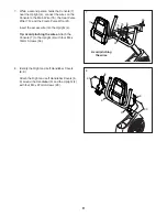
Page 9: ...1 Insert the excess wire into the Upright 4 Tip Avoid pinching the wires Attach the Console 7 to the Upright 4 with four M4 x 16mm Screws 56 7 7 4 75 91 76 56 Avoid pinching the wires 8 Identify the Right and Left Handlebar Covers 8 9 Attach the Right and Left Handlebar Covers 8 9 around the Handlebar 6 and the Upright 4 with four M4 x 22mm Screws 90 8 6 4 90 8 9 90 ...

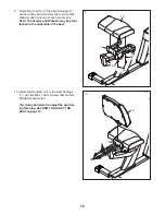
Page 10: ...e shown Note The Screws and Washers may be preat tached to the underside of the Seat 9 15 11 65 66 66 10 Attach the Backrest 13 to the Seat Carriage 11 with five M8 x 16mm Screws 60 and five M8 Split Washers 61 Tip It may be helpful to adjust the seat dur ing this step See HOW TO ADJUST THE SEAT on page 13 10 13 11 61 60 ...

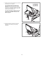
Page 11: ...2 attach the Pulse Bar to the Seat Carriage 11 with two M8 x 45mm Screws 63 and two M8 Split Washers 61 Tip It may be helpful to adjust the seat dur ing this step See HOW TO ADJUST THE SEAT on page 13 11 72 41 12 11 61 63 41 Avoid pinching the Pulse Bar Pulse Wire 72 12 Plug the Pulse Bar Pulse Wire 72 into the Receptacle 75 located in the Left Seat Shield 24 12 72 75 24 ...

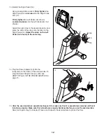
Page 12: ...he strap on the Left Pedal not shown in the same way 16 17 Strap Tab 13 14 Plug the Power Adapter 49 into the receptacle on the frame of the exercise bike To plug the Power Adapter into an outlet see HOW TO PLUG IN THE POWER ADAPTER on page 13 15 After the exercise bike is assembled inspect it to make sure that it is assembled correctly and that it functions properly Make sure that all parts are p...

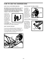
Page 13: ... all local codes and ordinances HOW TO ADJUST THE SEAT The seat can be adjusted forward or backward to the position that is the most comfortable To adjust the seat push downward on the seat handle slide the seat to the desired position and then pull upward on the seat handle to lock the seat in place HOW TO ADJUST THE PEDAL STRAPS To adjust the pedal straps first pull the ends of the straps off th...

Page 14: ...nsole also features an iFit mode that enables the console to communicate with your wireless network through an optional iFit module With the iFit mode you can download personalized workouts create your own workouts track your workout results race against other iFit users and access many other features To purchase an iFit module at any time go to www iFit com or call the telephone number on the fro...

Page 15: ...s display mode will show your heart rate when you use the handgrip heart rate monitor or an optional chest heart rate monitor see step 5 Resistance Resist This display mode will show the resistance level of the pedals for a few seconds each time the resistance level changes Speed This display mode will show your pedaling speed in miles per hour or kilometers per hour Time When the manual mode is s...

Page 16: ...heart symbol in the calorie display will flash each time your heart beats one or two dashes will appear and then your heart rate will be shown For the most accurate heart rate reading hold the contacts for at least 15 seconds If the display does not show your heart rate make sure that your hands are positioned as described Be careful not to move your hands excessively or to squeeze the contacts ti...

Page 17: ...of the profile will begin to flash If a different resis tance level and or target speed is programmed for the next segment the resistance level and or target speed will appear in the display for a few seconds to alert you The resistance of the pedals will then change As you exercise you will be prompted to keep your pedaling speed near the target speed for the cur rent segment When an upward point...

Page 18: ... speed that is comfortable for you You can manually change the resistance of the pedals as desired during the workout by pressing the One Touch Resistance buttons Note If you manually change the resistance during a calorie goal workout the length of the workout will adjust automatically to ensure that you meet your calorie goal Note The calorie goal is an estimate of the number of calories that yo...

Page 19: ...it but tons Before some workouts will download you must add them to your schedule on www iFit com Press the Map button the Train button or the Lose Wt button to download the next workout of that type in your schedule Press the Compete button to compete in a race that you have previously scheduled Press the Track button to re run a recent iFit work out from your schedule Next press the increase and...

Page 20: ... console you can also use the information mode to choose an audio setting for the voice of the personal trainer set a default menu check the status of the iFit module and check for downloads 1 Select the information mode To select the information mode press and hold down the Display button for a few seconds until the information mode appears in the display 2 View usage information The display will...

Page 21: ...e iFit sta tus display The words CHECK WIFI STATUS or CHECK USB STATUS will appear in the display Then press the Enter button After a few seconds the status of the iFit module will appear in the dis play To exit this display press and hold down the Display button for a few seconds 9 Check for downloads if desired Press the decrease button to view the downloads display The words SEND RECEIVE DATA w...

Page 22: ...the console use only a manufacturer supplied regulated power adapter HOW TO ADJUST THE REED SWITCH If the console does not display correct feedback the reed switch should be adjusted To adjust the reed switch first unplug the power adapter Using a flat screwdriver release the tabs on the Shield Cover 5 and pull the Shield Cover upward Locate the Reed Switch 46 Turn the Pulley 58 until a Magnet 29 ...

Page 23: ...t Next using a flat screwdriver release the tabs on the Shield Cover 5 and pull the Shield Cover upward Then remove all the screws from the Left and Right Front Shields 22 not shown there are three sizes of screws in the Front Shields note which size of screw you remove from each hole Then gently pull the Right Front Shield away from the frame Loosen the M6 x 20mm Hex Screw 78 Tighten the M10 x 50...

Page 24: ...ic Exercise If your goal is to strengthen your cardiovascular system you must perform aerobic exercise which is activity that requires large amounts of oxygen for prolonged periods of time For aerobic exercise adjust the intensity of your exercise until your heart rate is near the highest number in your training zone WORKOUT GUIDELINES Warming Up Start with 5 to 10 minutes of stretch ing and light...

Page 25: ...rge Washer 53 1 Snap Fastener 54 3 M4 x 25mm Screw 55 2 M4 x 10mm Flange Screw 56 16 M4 x 16mm Screw 57 3 M6 x 16mm Screw 58 1 Pulley 59 2 Crank Arm Cap 60 10 M8 x 16mm Screw 61 16 M8 Split Washer 62 4 M10 x 95mm Screw 63 2 M8 x 45mm Screw 64 2 5 16 Flange Screw 65 4 M6 x 50mm Screw 66 17 M6 Washer 67 2 1 4 x 14mm Screw 68 1 M4 x 13mm Bright Screw 69 8 1 4 x 16mm Screw 70 1 M4 x 13mm Flange Screw ...

Page 26: ...6 47 48 51 58 59 59 60 61 60 61 61 60 61 60 60 61 60 61 61 62 62 63 64 64 61 61 66 66 66 69 69 69 69 67 57 73 73 74 74 61 61 52 77 78 81 84 34 82 56 82 86 56 89 90 90 56 88 56 56 56 79 56 56 76 75 70 72 66 66 50 68 66 50 50 50 50 50 50 50 49 32 85 79 79 79 85 85 87 55 85 79 29 29 79 86 91 92 EXPLODED DRAWING A Model No NTEVEX74913 0 R0413A ...

Page 27: ...27 10 13 14 15 22 21 24 23 65 65 66 66 80 80 79 79 79 79 79 79 79 54 79 79 54 79 79 79 54 71 71 79 53 25 EXPLODED DRAWING B Model No NTEVEX74913 0 R0413A ...

Page 28: ... the EXPLODED DRAWING near the end of this manual ORDERING REPLACEMENT PARTS This electronic product must not be disposed of in municipal waste To preserve the environment this product must be recycled after its useful life as required by law Please use recycling facilities that are authorized to collect this type of waste in your area In doing so you will help to conserve natural resources and im...

Reviews: