background image

28

SYMPTOM: The walking belt slows when walked on

a.  

Use only a surge suppressor that meets all of the 

specifications described on page 14.

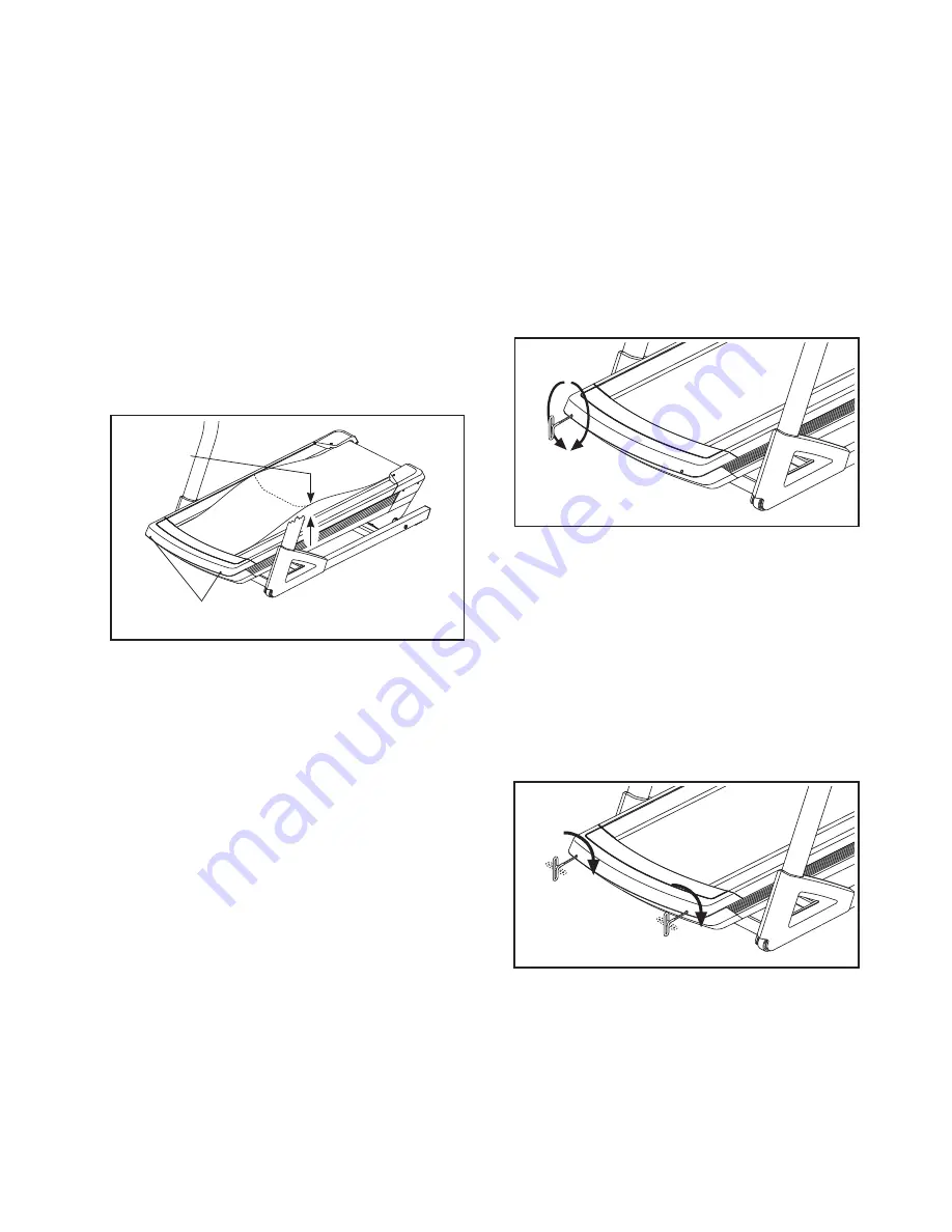
b.    If the walking belt is overtightened, incline trainer 

performance may decrease and the walking belt 

may become damaged. First, adjust the incline to 

40 percent. Then, remove the key and UNPLUG 

THE POWER CORD. Using the hex key, turn both 

idler roller screws counterclockwise, 1/4 of a turn. 

When the walking belt is properly tightened, you 

should be able to lift each edge of the walking belt 

3 to 4 in. (8 to 10 cm) off the walking platform. Be 

careful to keep the walking belt centered. Then, 

plug in the power cord, insert the key, and run the 

incline trainer for a few minutes. Repeat until the 

walking belt is properly tightened.

c.  

Your incline trainer features a walking belt coated 

with high-performance lubricant. IMPORTANT: 

Never apply silicone spray or other substances 

to the walking belt or the walking platform 

unless instructed to do so by an authorized 

service representative. Such substances may 

deteriorate the walking belt and cause exces-

sive wear. If you suspect that the walking belt 

needs more lubricant, see the front cover of this 

manual.

d.   If the walking belt still slows when walked on, see 

the front cover of this manual.

SYMPTOM: The walking belt is off-center or slips 

when walked on

a.   If the walking belt is off-center, first adjust 

the incline to 40 percent. Remove the key and 

UNPLUG THE POWER CORD. If the walking belt 

has shifted to the left, use the hex key to turn the 

left idler roller screw clockwise 1/2 of a turn; if the 

walking belt has shifted to the right, turn the left 

idler roller screw counterclockwise 1/2 of a turn. Be 

careful not to overtighten the walking belt. Then, 

plug in the power cord, insert the key, and run the 

incline trainer for a few minutes. Repeat until the 

walking belt is centered. 

b.   If the walking belt slips when walked on, first 

adjust the incline to 40 percent. Remove the key 

and UNPLUG THE POWER CORD. Using the hex 

key, turn both idler roller screws clockwise, 1/4 of a 

turn. When the walking belt is correctly tightened, 

you should be able to lift each edge of the walking 

belt 3 to 4 in. (8 to 10 cm) off the walking platform. 

Be careful to keep the walking belt centered. Then, 

plug in the power cord, insert the key, and care-

fully walk on the incline trainer for a few minutes. 

Repeat until the walking belt is properly tightened.

3–4 in.

b

Idler Roller Screws

a

b

Summary of Contents for Incline Trainer X11

Page 1: ... CONTACT THE STORE please contact Customer Care IMPORTANT Please register this product see the limited warranty on the back cover of this manual before contacting Customer Care CALL TOLL FREE 1 800 TO BE FIT 1 800 862 3348 Mon Fri 6 a m 6 p m MT Sat 8 a m 4 p m MT ON THE WEB www nordictrackservice com Model No NTL24012 0 Serial No Write the serial number in the space above for reference www nordic...

Page 2: ... Apply the decal in the location shown Note The decals may not be shown at actual size 271317 WARNING DECAL PLACEMENT WARNING DECAL PLACEMENT 2 IMPORTANT PRECAUTIONS 3 BEFORE YOU BEGIN 5 PART IDENTIFICATION CHART 6 ASSEMBLY 7 THE CHEST HEART RATE MONITOR 13 OPERATION AND ADJUSTMENT 14 HOW TO MOVE THE INCLINE TRAINER 26 TROUBLESHOOTING 27 EXERCISE GUIDELINES 29 PART LIST 30 EXPLODED DRAWING 31 ORDE...

Page 3: ... men and women Always wear athletic shoes Never use the incline trainer with bare feet wearing only stockings or in sandals 12 Plug the power cord into a surge suppressor not included and plug the surge suppres sor into an appropriate outlet see page 14 To avoid overloading the circuit do not plug other electrical devices except for low power devices such as cell phone chargers into the surge supp...

Page 4: ...r switch and unplug the power cord when the incline trainer is not in use 22 Do not attempt to move the incline trainer until it is properly assembled See ASSEMBLY on page 7 and HOW TO MOVE THE INCLINE TRAINER on page 26 You must be able to safely lift 45 lbs 20 kg to raise lower or move the incline trainer 23 Never insert any object into any opening on the incline trainer 24 Inspect and properly ...

Page 5: ...he front cover of this manual To help us assist you note the product model number and serial number before contacting us The model number and the location of the serial number decal are shown on the front cover of this manual Before reading further please familiarize yourself with the parts that are labeled in the drawing below BEFORE YOU BEGIN Handrail Console Fan Key Clip Power Switch Walking Pl...

Page 6: ...er following the key number is the quantity used for assembly Note If a part is not in the hardware kit check to see if it is preat tached Extra parts may be included 8 x 3 4 Screw 1 10 8 x 1 Tek Screw 2 4 3 8 Star Washer 8 10 5 16 Star Washer 9 4 8 x 1 1 4 Screw 36 2 3 8 x 3 1 2 Screw 5 4 8 x 3 4 Machine Screw 16 9 5 16 x 2 1 2 Screw 4 4 5 16 x 5 8 Screw 11 4 3 8 x 5 1 2 Screw 5 8 3 8 x 2 3 4 Scr...

Page 7: ...obile phone or smartphone to read the QR code at the right Assembly requires two persons Place all parts in a cleared area and remove the packing materials Do not dispose of the packing materials until you finish all assembly steps After shipping there may be an oily substance on the exterior of the incline trainer This is normal If there is an oily substance on the incline trainer wipe it off wit...

Page 8: ...en them Make sure not to pinch the Upright Wire not shown in the Upright Attach the other Upright not shown as described above Note There is not a wire on the left side 2 77 17 80 8 8 5 3 89 37 A A 3 Set the Console 37 face down on a soft surface to avoid scraching the Console Remove and discard the four screws A from the Console Base Back 89 Lift off the Console Base Back ...

Page 9: ...sbar to align the holes Then tighten the two 8 x 1 Screws 102 Attach the left Upright not shown to the Console Crossbar 101 on the other side of the incline trainer as described above 4 Have a second person hold the console assem bly near the Uprights 77 Insert the console wire and the R pulse wire from the console assembly through the indicated tie Connect the Upright Wire 78 to the console wire ...

Page 10: ...the two R pulse wires L R R 7 5 L Pulse Wire Start First 93 77 8 R Pulse Wires Console Assembly 6 Tighten two 8 x 3 4 Screws 1 into the Console Base 87 Do not overtighten the Screws Identify the Right Handrail Assembly 93 Hold the Right Handrail Assembly near the right Upright 77 Insert the pulse wire from the Right Handrail Assembly into the hole in the top of the Upright and pull it out of the e...

Page 11: ...e left Upright 77 Insert the pulse wire from the Left Handrail Assembly into the hole in the top of the Upright and pull it out of the end of the Upright Set the Left Handrail Assembly 86 on the left Upright 77 Make sure that no wires are pinched Attach the Left Handrail Assembly 86 with two 3 8 x 5 1 2 Screws 5 and two 3 8 Star Washers 8 Note Start the lower Screw first Insert the pulse wire thro...

Page 12: ...t Inside Cover 3 and the Left Outside Cover 106 Next hold the Left Inside Cover against the left Upright 77 Then hold the Left Outside Cover against the Left Inside Cover Attach the Left Outside Cover 106 to the Left Inside Cover 3 with three 8 x 3 4 Screws 1 Start all three Screws and then tighten them Attach the Right Inside Cover and the Right Outside Cover not shown as described above 58 10 14...

Page 13: ...atures above 122 F 50 C or below 14 F 10 C Do not excessively bend or stretch the sensor when using or storing the heart rate monitor To clean the sensor use a damp cloth and a small amount of mild soap Then wipe the sensor with a damp cloth and thoroughly dry it with a soft towel Never use alcohol abrasives or chemicals to clean the sensor Hand wash and air dry the chest strap TROUBLESHOOTING If ...

Page 14: ...e power cord into a surge suppressor and plug the surge suppressor into an appropriate outlet that is properly installed and grounded in accordance with all local codes and ordinances The outlet must be on a nominal 120 volt circuit capable of carrying 15 or more amps To avoid overloading the circuit do not plug other electrical devices except for low power devices such as cell phone chargers into...

Page 15: ...d and incline of the incline trainer as it guides you through an effective exercise session In addition you can set a calorie time distance or pace goal When you use the manual mode you can change the speed and incline of the incline trainer with the touch of a button As you exercise the console will display instant exer cise feedback You can also measure your heart rate using the handgrip heart r...

Page 16: ...he position of the clip HOW TO USE THE TOUCH SCREEN The console features a tablet with a full color touch screen The following information will help you become familiar with the tablet s advanced technology The console functions similarly to other tablets You can slide or flick your finger against the screen to move certain images on the screen such as the displays in a workout see step 5 on page ...

Page 17: ...on in the upper right corner of the screen The browser will open to the iFit com registration page Touch the Buy Now button to register for an iFit account If you have an activation code select the code activation option Then follow the prompts on the screen to sign up for your iFit membership The console is now ready for you to begin working out The following pages explain the various workouts an...

Page 18: ... as desired To change the incline of the incline trainer press the Incline increase and decrease buttons or one of the numbered 1 Step Incline Decline buttons Each time you press one of the buttons the incline will gradually change until it reaches the selected incline setting Note For your safety as you adjust the incline set ting to negative levels or to levels above 15 the maximum speed of the ...

Page 19: ...rate will be shown For the most accurate heart rate reading continue to hold the contacts for about 15 seconds 7 Turn on the fan if desired The fan features several speed settings and an auto mode When the auto mode is selected the speed of the fan will automatically increase and decrease as the speed of the walking belt increases and decreases Press the Manual fan button repeatedly to select a fa...

Page 20: ...he last segment ends The walking belt will then slow to a stop and a workout summary will appear on the screen After you view the workout summary touch the Finish button to return to the main menu You may also be able to either save or publish your results using one of the options on the screen If the speed and or incline settings are too high or too low at any time during the workout you can over...

Page 21: ...you touch the button the walking belt will begin to move Hold the handrails and begin walking The workout will function in the same way as the manual mode see pages 18 and 19 The workout will continue until you reach the goal that you set The walking belt will then slow to a stop and a workout summary will appear on the screen After you view the workout summary touch the Finish button to return to...

Page 22: ...iFit buttons on the console To switch users within the account touch the user button near the lower right corner of the screen Before some workouts will download you must add them to your schedule on iFit com For more information about the iFit workouts please see www iFit com When you select an iFit workout the screen will show the name duration and distance of the work out The screen will also s...

Page 23: ...ne trainer is dis played in a store While the demo mode is turned on the console will function normally when you plug in the power cord press the power switch into the reset position and insert the key into the console However when you remove the key the screen will show a demo presentation To turn on or turn off the display demo mode first touch the Demo Mode button Next touch the On checkbox or ...

Page 24: ...egin automatically To avoid damaging the incline trainer do not turn off the power or remove the key while the firmware is being updated The screen will show the progress of the update When the update is complete the incline trainer will turn off and then turn back on If it does not press the power switch into the off position Wait for sev eral seconds and then press the power switch into the rese...

Page 25: ...ks If the network has a password touch the password entry box A keyboard will appear on the screen To view the password as you type it touch the Show Password checkbox To use the keyboard see HOW TO USE THE TOUCH SCREEN on page 16 When the console is connected to your wireless network the WiFi menu option at the top of the screen will display the word CONNECTED Then press the back button on the co...

Page 26: ...rease and decrease buttons on the console If you are using a personal CD player and the CD skips set the CD player on the floor or another flat surface instead of on the console Before moving the incline trainer insert the key into the console raise the incline to the maximum incline level remove the key and unplug the power cord Due to the size and weight of the incline trainer moving it requires...

Page 27: ... then press the switch back in b Make sure that the power cord is plugged in If the power cord is plugged in unplug it wait for five minutes and then plug it back in c Remove the key from the console and then reinsert it d If the incline trainer still will not run please see the front cover of this manual SYMPTOM The console displays remain lit when you remove the key from the console a The consol...

Page 28: ...king belt needs more lubricant see the front cover of this manual d If the walking belt still slows when walked on see the front cover of this manual SYMPTOM The walking belt is off center or slips when walked on a If the walking belt is off center first adjust the incline to 40 percent Remove the key and UNPLUG THE POWER CORD If the walking belt has shifted to the left use the hex key to turn the...

Page 29: ...ic Exercise If your goal is to strengthen your cardiovascular system you must perform aerobic exercise which is activity that requires large amounts of oxygen for prolonged periods of time For aerobic exercise adjust the intensity of your exercise until your heart rate is near the highest number in your training zone WORKOUT GUIDELINES Warming Up Start with 5 to 10 minutes of stretch ing and light...

Page 30: ... 54 1 Belly Pan 55 1 Reed Switch 56 1 Reed Switch Clamp 57 2 Axle 58 1 Frame 59 1 Electronics Cover 60 2 Incline Motor Spacer 61 1 Front Belly Pan 62 1 Left Side Deckrail 63 1 Top Incline Motor Cover 64 1 Incline Motor 65 1 Bottom Incline Motor Cover 66 1 Right Side Deckrail 67 2 Wire Clamp 68 1 Left Foot Rail 69 1 Resistor 70 1 Electronics Plate 71 1 Controller 72 1 Right Foot Rail 73 4 Cushion C...

Page 31: ... 35 35 35 39 21 21 23 23 23 25 25 42 41 48 44 43 47 43 40 23 1 1 1 68 62 72 66 35 35 35 35 35 35 35 35 1 1 1 1 45 36 36 18 18 85 85 1 1 1 1 1 1 1 28 28 28 28 28 28 28 28 1 1 1 1 1 18 18 35 35 35 81 EXPLODED DRAWING A Model No NTL24012 0 R1012A ...

Page 32: ...29 33 22 31 69 13 13 70 13 30 30 13 30 27 27 32 46 33 1 32 63 65 64 1 1 1 46 46 60 56 20 22 31 55 46 74 73 79 74 73 79 73 49 61 107 15 26 26 13 59 13 13 1 107 13 71 1 7 7 7 7 73 EXPLODED DRAWING B Model No NTL24012 0 R1012A ...

Page 33: ...33 2 10 2 10 1 1 1 1 1 1 94 80 92 24 57 84 57 84 24 106 3 78 81 82 83 82 81 8 17 8 17 14 14 14 14 EXPLODED DRAWING C Model No NTL24012 0 R1012A ...

Page 34: ...34 77 78 4 9 77 8 5 8 5 103 76 1 102 102 104 104 1 1 1 101 11 11 98 98 8 5 8 5 4 9 8 8 1 1 1 1 97 13 32 12 6 32 12 6 105 105 86 93 EXPLODED DRAWING D Model No NTL24012 0 R1012A ...

Page 35: ...35 1 1 1 1 16 1 1 1 19 87 1 1 67 96 96 100 99 99 37 88 89 16 16 16 16 16 16 16 34 34 100 100 100 90 91 1 1 1 1 95 EXPLODED DRAWING E Model No NTL24012 0 R1012A ...

Page 36: ... not responsible or liable for indirect special or consequential damages arising out of or in con nection with the use or performance of the product damages with respect to any economic loss loss of property loss of revenues or profits loss of enjoyment or use or costs of removal or installation or other consequential damages of any kind Some states do not allow the exclusion or limitation of inci...

Reviews: