background image

9

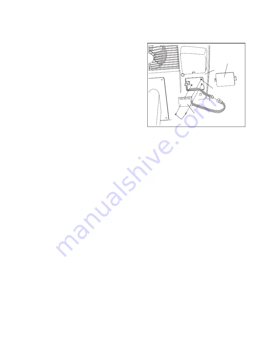
INSTALLING THE RECEIVER FOR THE OPTIONAL CHEST PULSE SENSOR

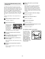
If you purchase the optional chest pulse sensor (see page 21), follow the steps below to install the receiver
included with the chest pulse sensor.

Remove the access door from the underside of the
Console (4). Note: You may need to use a small standard
screwdriver to remove the access door.

Slide the receiver onto the indicated plastic pin on the
Console (4); make sure that the receiver is oriented
exactly as shown. 
Locate the two small screws included
with the chest pulse sensor. Attach the receiver to the
Console with the two screws as shown.

Connect the wire on the receiver to the indicated wire on
the Console (4). 

Reattach the access door. Make sure that no wires are
pinched. 
Note: The other wires included with the chest
pulse sensor may be discarded.

Pin

Access

Door

Wire

Screws

4

Receiver

Summary of Contents for NTC0894.1

Page 1: ...re com mitted to providing complete customer satisfaction If you have questions or if parts are damaged or missing PLEASE CONTACT OUR CUSTOMER SERVICE DEPARTMENT DIRECTLY CALL TOLL FREE 1 888 825 2588...

Page 2: ...BLY 5 HOW TO OPERATE THE EXERCISE CYCLE 10 MAINTENANCE AND TROUBLESHOOTING 22 EXERCISE GUIDELINES 23 PART LIST 25 EXPLODED DRAWING 26 HOW TO ORDER REPLACEMENT PARTS Back Cover LIMITED WARRANTY Back Co...

Page 3: ...ce any worn parts immediately 7 Keep children under the age of 12 and pets away from the exercise cycle at all times 8 Wear appropriate clothing when exercising do not wear loose clothing that could b...

Page 4: ...have questions after reading this manual see the front cover of this manual To help us assist you please note the product model number and serial number before call ing The model number is NTC0894 1...

Page 5: ...quantity needed for assembly Note Some small parts may have been pre assembled for shipping If a part is not in the parts bag check to see if it has been pre assembled M10 Nylon Locknut 63 2 M8 Split...

Page 6: ...ing this step 16 1 55 55 54 54 2 43 Wire 4 Identify the Left Handlebar 70 which is marked with a sticker While another person holds the Left Handlebar near the Upright 2 connect the left Pulse Sensor...

Page 7: ...wire harness on the Console 4 Connect the Pulse Wire 3 to the pulse wire on the Console Next locate the two ground wires that are connected with a screw to the Upright 2 Connect the ground wires to th...

Page 8: ...tant Tighten both Pedals as firmly as possible After using the exercise cycle for one week retighten the Pedals For best performance the Pedals must be kept tightened Identify the Left Pedal Strap 25...

Page 9: ...remove the access door Slide the receiver onto the indicated plastic pin on the Console 4 make sure that the receiver is oriented exactly as shown Locate the two small screws included with the chest p...

Page 10: ...ntil the rocking motion is eliminated HOW TO ADJUST THE SEAT The seat can be adjusted to the posi tion that is the most comfortable for you To adjust the seat pull the seat knob slide the seat for war...

Page 11: ...arget heart rate as you exercise The console also features iFIT com interactive technol ogy Having iFIT com technology is like having a per sonal trainer in your home Using the included audio cable yo...

Page 12: ...und the track will light in succession until the entire track is lit The track will then dark en and the indicators will again begin to light in succession The Training Zone bar The Training Zone bar...

Page 13: ...t Rate indicator above the right dis play will begin to flash one or two dashes will appear in the right display and then your heart rate will be shown For the most accurate heart rate reading hold th...

Page 14: ...an indicator to the left of any lit indicator is flashing see drawing b decrease your pace When no indicator is flashing your pace matches the pace setting for the current segment Important The pace...

Page 15: ...se heart rate pro gram 2 is designed to keep your heart rate between 50 and 85 of your maximum heart rate Follow the steps below to use a heart rate program Begin pedaling to activate the console See...

Page 16: ...r will help you to keep your heart rate near the heart rate setting for the current segment The lit indicators in the bar will show your actual pace When you hold the handgrip pulse sensor or wear the...

Page 17: ...Y adapter available at electronics stores Plug the Y adapter into the PHONES jack on your CD player Plug your headphones into the other side of the Y adapter HOW TO CONNECT YOUR PORTABLE STEREO Note I...

Page 18: ...adapter Plug the Y adapter into the LINE OUT jack on your stereo HOW TO CONNECT YOUR COMPUTER Note If your computer has a 1 8 LINE OUT jack see instruction A If your computer has only a PHONES jack se...

Page 19: ...e adapter into the AUDIO OUT jack on your VCR B Plug one end of the audio cable into the jack beneath the console Plug the other end of the cable into the adapter Plug the adapter into an RCA Y adapte...

Page 20: ...oment after the play button is pressed your personal trainer will begin guiding you through your workout Simply follow your personal trainer s instructions The program will function in almost the same...

Page 21: ...n our Web site to select a program Read and follow the on line instructions for using a program Follow the on line instructions to start the program When you start the program an on screen count down...

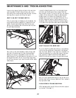
Page 22: ...the Magnet 30 is aligned with the Reed Switch Loosen but do not remove the indicat ed M4 x 16mm Screw 57 Slide the Reed Switch slightly closer to or away from the Magnet Then retighten the Screw Turn...

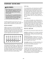
Page 23: ...exercise must be aerobic Aerobic exercise is activity that requires large amounts of oxygen for prolonged periods of time This increases the demand on the heart to pump blood to the muscles and on th...

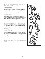
Page 24: ...les Stretch With one leg in front of the other reach forward and place your hands against a wall Keep your back leg straight and your back foot flat on the floor Bend your front leg lean forward and m...

Page 25: ...ing 59 2 M6 x 50mm Bolt 60 4 M8 Washer 61 1 M10 Washer 62 1 Backrest 63 5 M10 Nylon Locknut 64 4 M5 Nylon Locknut 65 6 M4 x 25mm Screw 66 1 Backrest Frame Endcap 67 1 Idler Bolt 68 4 M8 x 14mm Flat He...

Page 26: ...26 4 7 11 9 10 86 12 26 27 66 58 42 57 62 52 65 86 65 65 93 57 58 58 79 79 80 80 80 80 63 82 83 83 60 60 55 55 55 55 57 93 57 57 57 73 73 EXPLODED DRAWING A Model No NTC0894 1 R0605A...

Page 27: ...1 43 44 67 68 49 51 57 57 59 64 45 57 72 70 33 21 23 18 51 22 24 25 33 33 32 89 37 36 69 33 63 68 71 71 46 57 57 76 28 74 75 75 63 77 78 28 84 84 85 3 71 91 61 92 90 90 88 75 83 87 87 94 95 30 29 31 9...

Page 28: ...IMPORTANT THAT YOU READ THE MANUAL before operating the Product Remember to do the periodic maintenance requirements specified in the Manual to assure proper operation and your continued satisfaction...

Reviews: