background image

21

1

1

Frame

2

1

Upright

3

1

Left Handlebar

4

1

Console

5

1

Right Handlebar

6

2

Pulse Sensor

7

1

Adjustment Knob

8

1

Backrest

9

1

Seat

10 1  Backrest 

Cover

11 1  Seat 

Bracket

12 

Seat Bracket Endcap

13 

Left Front Side Shield

14 

Right Front Side Shield

15 

1

Left Front Stabilizer

16 1  Rear 

Stabilizer

17

2 Wheel

18 

Right Pedal Strap

19 

2

Leveling Foot

20 2  Upright 

Bushing

21 1  Right 

Pedal

22 

1

Left Pedal

23 1  Right 

Crank 

Arm

24 1  Left 

Crank 

Arm

25 

1

Left Pedal Strap

26 

Left Side Shield

27 

Right Side Shield

28 

1

Large Snap Ring

29 1  Pulley

30 1  Magnet

31 

1

Crank

32 1  Steel 

Washer

33 

2

Crank Bearing

34 1  Flywheel

35 1  “C” 

Magnet

36 1  Resistance 

Cable

37 1  Spring

38 1  Resistance 

Motor

39 1  Idler

40 

Right Front Stabilizer

41 1  Seat 

Carriage

42 

Upper Wire Harness

43 

Lower Wire Harness

44 1  Flywheel 

Spacer

45 1  Clamp

46 1  Reed 

Switch/Wire

47 1  Drive 

Belt

48 

Rear Stabilizer Endcap

49

1

Foam Grip

50 2  Flange 

Screw

51

1

Pulse Extension Wire

52 

M8 x 50mm Button Screw

53 1  Pillow 

Block

54 

M8 x 16mm Button Screw

55 

14

M8 Split Washer

56 

Seat Rail Endcap

57 

11 

M4 x 16mm Screw

58 

M6 x 13mm Button Screw

59 

10 

Small Snap Ring

60 

M4 x 22mm Screw

61 1

Snap 

Ring

62 

M10 x 63mm Bolt Set

63 4  Wheel 

Bushing

64 2  M6 

Nut

65 

1

Stop Block

66 

Front Stabilizer Endcap

67 

Seat Carriage Endcap

68 

1

M8 x 38mm Bolt

69

2

Wheel Bolt

70

1

M6 x 38mm Bolt

71

10

Seat Carriage Wheel

72

8

M6 Nylon Locknut

73

4

M6 x 20mm Button Bolt

74

1

Water Bottle Holder

75

2

Pulse Wire

76

4

M6 x 36mm Button Bolt

77

4

M8 x 19mm Button Screw

78

4

M10 x 36mm Button Screw

79

3

M8 Nylon Locknut

80

4

M4 x 16mm Round Head Screw

81

4

M6 x 16mm Button Screw

82

4

M4 x 16mm Flange Screw

83

1

Frame Endcap

84

9

M4 x 19mm Screw

85

2

Crank Cover

86

1

M8 x 52mm Button Bolt

87

1

M8 Flange Nut

88

4

M6 Washer

89

2

Wheel Washer

#

1

Allen Wrench

#

1

User’s Manual

Note: “#” indicates a non-illustrated part. Specifications are subject to change without notice. See the back cover

of this manual for information about ordering replacement parts.

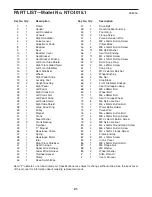
PART LIST—Model No. NTC4015.1

R0805A

Key No. Qty.

Description

Key No. Qty.

Description

Summary of Contents for NTC4015.1

Page 1: ...e Visit our website at www healthrider com new products prizes fitness tips and much more Visit our website at www nordictrack com new products prizes fitness tips and much more QUESTIONS As a manufac...

Page 2: ...times 7 Wear appropriate clothes when exercising do not wear loose clothes that could become caught on the exercise cycle Always wear athletic shoes for foot protection 8 The exercise cycle should no...

Page 3: ...ise cycle If you have questions after reading this manual please see the front cover of this manual To help us assist you note the product model number and serial number before calling The model numbe...

Page 4: ...needed for assembly Note Some small parts may have been pre attached If a part is not in the parts bag check to see if it has been pre attached M10 x 63mm Bolt Set 62 1 M6 x 36mm Button Bolt 76 4 M6...

Page 5: ...rting the Upright into the Frame Attach the Upright with an M10 x 63mm Bolt Set 62 Be careful to avoid pinch ing the Wire Harnesses 42 43 Attach the Water Bottle Holder 74 to the Upright 2 with two M4...

Page 6: ...o the Backrest 8 and hold the Backrest Cover in place Next attach the Backrest and the Backrest Cover to the Seat Bracket 11 with four M10 x 36mm Button Screws 78 8 6 While another person holds the Co...

Page 7: ...the end of the Left Pedal Strap onto the tab on the Left Pedal 22 Adjust the Right Pedal Strap not shown in the same way 11 25 22 24 Tab 10 Attach the Seat Bracket 11 to the Seat Carriage 41 with four...

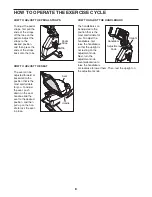
Page 8: ...To adjust the seat push down on the seat handle slide the seat to the desired position and then pull up on the han dle to lock the seat in place HOW TO ADJUST THE HANDLEBARS The handlebars can be adj...

Page 9: ...e Using the included stereo audio cable you can connect the exercise cycle to your portable stereo home stereo computer or VCR and play special iFIT com CD and video programs iFIT com CDs and videocas...

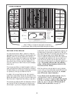
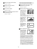
Page 10: ...il the entire track is lit The track will then dark en and the indicators will again begin to light in succession The Training Zones bar The Training Zones bar will show the approximate inten sity lev...

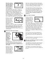
Page 11: ...to hold the handgrip pulse sensor the lower display will show your heart rate for up to 30 seconds The display will then show your heart rate along with the other modes If your heart rate is not show...

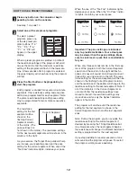
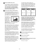
Page 12: ...ur pace When the one of the Too Fast indicators lights decrease your pace When the On Pace indica tor lights maintain your current pace Important The pace settings are intended only to provide motivat...

Page 13: ...of the target heart rate settings of the pro gram will scroll across the matrix If the second heart rate program P 2 is selected a pulse symbol will appear in the matrix Enter a target heart rate sett...

Page 14: ...re the program ends During both heart rate programs the console will regularly compare your heart rate to the tar get heart rate setting If your heart rate is too far below or above the target heart r...

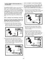
Page 15: ...pter into the PHONES jack on your CD player Plug your headphones into the other side of the Y adapter HOW TO CONNECT YOUR PORTABLE STEREO Note If your stereo has an RCA type AUDIO OUT jack see instruc...

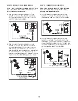
Page 16: ...OUT jack on your stereo HOW TO CONNECT YOUR COMPUTER Note If your computer has a 1 8 LINE OUT jack see instruction A If your computer has only a PHONES jack see instruction B A Plug one end of the aud...

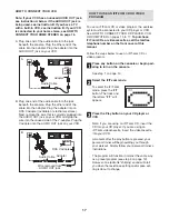
Page 17: ...elephone number on the front cover of this manual Follow the steps below to use an iFIT com CD or video program Press any button on the console or begin ped aling to turn on the console See step 1 on...

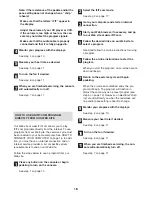
Page 18: ...ystem requirements is found on our Web site Follow the steps below to use a program from our Web site Press any button on the console or begin pedaling to turn on the console See step 1 on page 10 Sel...

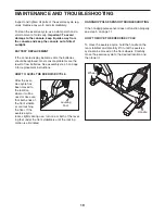
Page 19: ...fter the exer cise cycle has been moved to the location where it will be used make sure that both ends of the front stabiliz er are touching the floor If the exercise cycle rocks slightly during use t...

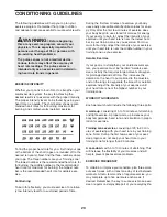
Page 20: ...xercise Aerobic Exercise If your goal is to strengthen your cardiovascular sys tem your exercise must be aerobic Aerobic exer cise is activity that requires large amounts of oxygen for prolonged perio...

Page 21: ...ion Wire 52 4 M8 x 50mm Button Screw 53 1 Pillow Block 54 6 M8 x 16mm Button Screw 55 14 M8 Split Washer 56 1 Seat Rail Endcap 57 11 M4 x 16mm Screw 58 4 M6 x 13mm Button Screw 59 10 Small Snap Ring 6...

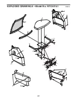
Page 22: ...22 13 14 57 57 84 9 41 11 71 71 71 71 71 71 59 59 59 8 10 27 26 12 12 57 57 84 77 77 77 77 78 78 81 55 55 55 49 67 84 84 84 84 88 88 55 59 71 59 89 EXPLODED DRAWING A Model No NTC4015 1 R0805A...

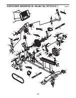
Page 23: ...63 79 39 68 82 38 36 35 37 79 64 70 23 32 50 33 30 29 31 73 73 72 72 21 18 75 75 4 80 80 60 74 7 5 6 3 6 2 15 19 66 54 17 55 63 63 69 79 83 57 25 22 43 47 42 51 24 33 28 50 45 46 57 20 20 56 62 62 65...

Page 24: ...ANT THAT YOU READ THE MANUAL before operating the Product Remember to do the periodic maintenance requirements specified in the Manual to assure proper operation and your continued satisfaction HOW TO...

Reviews: