
11
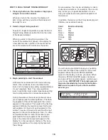
HOW TO PLUG IN THE POWER CORD
This product must be grounded.
If it should mal-
function or break down, grounding provides a path of
least resistance for electric current to reduce the risk
of electric shock. This product is equipped with a cord
having an equipment-grounding conductor and a
grounding plug.
Plug the power cord into an appro-
priate outlet that is properly installed and
grounded in accordance with all local codes and
ordinances. This product is for use on a nominal
120-volt circuit. IMPORTANT: The elliptical exer-
ciser is not compatible with GFCI-equipped out-
lets.
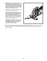
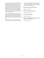
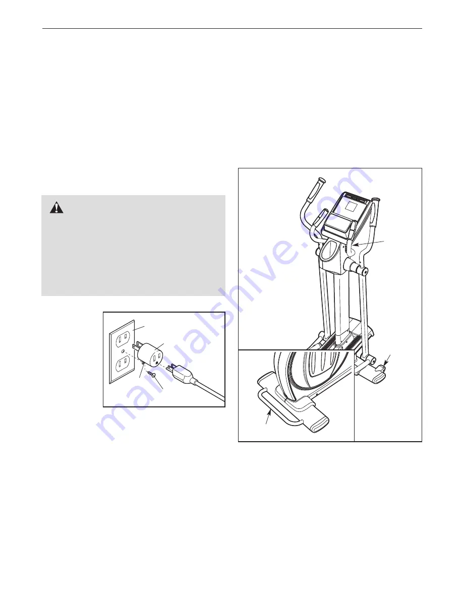
A temporary
adapter may
be used to
connect the
power cord to
a 2-pole
receptacle as
shown at the
right if a prop-
erly grounded
outlet is not
available. The
temporary adapter should be used only until a prop-
erly grounded outlet can be installed by a qualified
electrician.
The green-colored rigid ear, lug, or the like extending
from the adapter must be connected to a permanent
ground such as a properly grounded outlet box cover.
Whenever the adapter is used, it must be held in
place by a metal screw.
Some 2-pole receptacle out-
let box covers are not grounded. Contact a quali-
fied electrician to determine if the outlet box cover
is grounded before using an adapter.
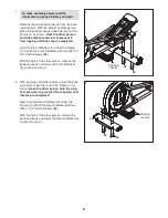
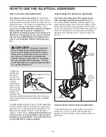
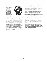
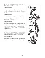
HOW TO MOVE THE ELLIPTICAL EXERCISER
Due to the size and weight of the elliptical exer-
ciser, moving it requires two persons.
Stand in
front of the elliptical exerciser, hold the upright, and
place one foot against one of the front wheels. Pull on
the upright and have a second person lift the handle
on the rear of the frame until the elliptical exerciser will
roll on the front wheels. Carefully move the elliptical
exerciser to the desired location, and then lower it to
the floor.
HOW TO LEVEL THE ELLIPTICAL EXERCISER
If the elliptical exerciser rocks slightly on your floor
during use, turn one or both of the leveling feet
beneath the rear stabilizer until the rocking motion is
eliminated.
DANGER:
Improper connection
of the equipment-grounding conductor can
result in an increased risk of electric shock.
Check with a qualified electrician or service-
man if you are in doubt as to whether the
product is properly grounded. Do not modify
the plug provided with the product—if it will
not fit the outlet, have a proper outlet installed
by a qualified electrician.
Grounded Outlet Box
Adapter
Lug
Metal Screw
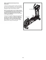
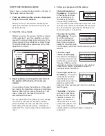
HOW TO USE THE ELLIPTICAL EXERCISER
Place
your foot
here
Lift here
Pull on
upright


