background image

19

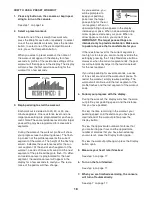
HOW TO USE A HEART RATE WORKOUT

1. Press any button on the console or begin ped-

aling to turn on the console.

See step 1 on page 16.

2. Select a heart rate workout.

To select one of the heart rate workouts, press the

Heart Rate button repeatedly until the words

HEART RATE 1 or HEART RATE 2 appear in the

display.

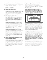
3. Enter a target heart rate setting.

A few seconds after you select a heart rate work-

out, the words ENTER HEART RATE will appear

in the display and the number 110 will begin to

flash.

During heart rate workout 1,

the same target

heart rate setting will be programmed for all seg-

ments of the workout. If you have selected heart

rate workout 1, press the increase and decrease

buttons below the Odometer button to enter the

desired target heart rate setting (see EXERCISE

INTENSITY on page 22).

During heart rate workout 2,

different target

heart rate settings will be programmed for different

segments of the workout. If you have selected

heart rate workout 2, press the increase and

decrease buttons below the Odometer button to

enter the desired maximum target heart rate set-

ting for the workout (see EXERCISE INTENSITY

on page 22).

4. Hold the handgrip pulse sensor or put on the

optional chest pulse sensor.

It is not necessary to hold the handgrip pulse sen-

sor continuously during heart rate workouts; how-

ever, you should hold the handgrip pulse sensor

frequently for the workouts to operate properly.

Each time you hold the handgrip pulse sensor,

keep your hands on the metal contacts for at

least 30 seconds.

5. Begin pedaling to start the workout.

Heart rate workout 1

is divided into 40 one-

minute segments. Note: For a shorter workout,

stop exercising or select a different workout before

the workout ends.

Heart rate workout 2

is divided into 30 one-

minute segments. One target heart rate setting is

programmed for each segment. Note: The same

target heart rate setting may be programmed for

consecutive segments.

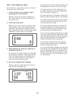
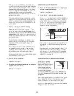
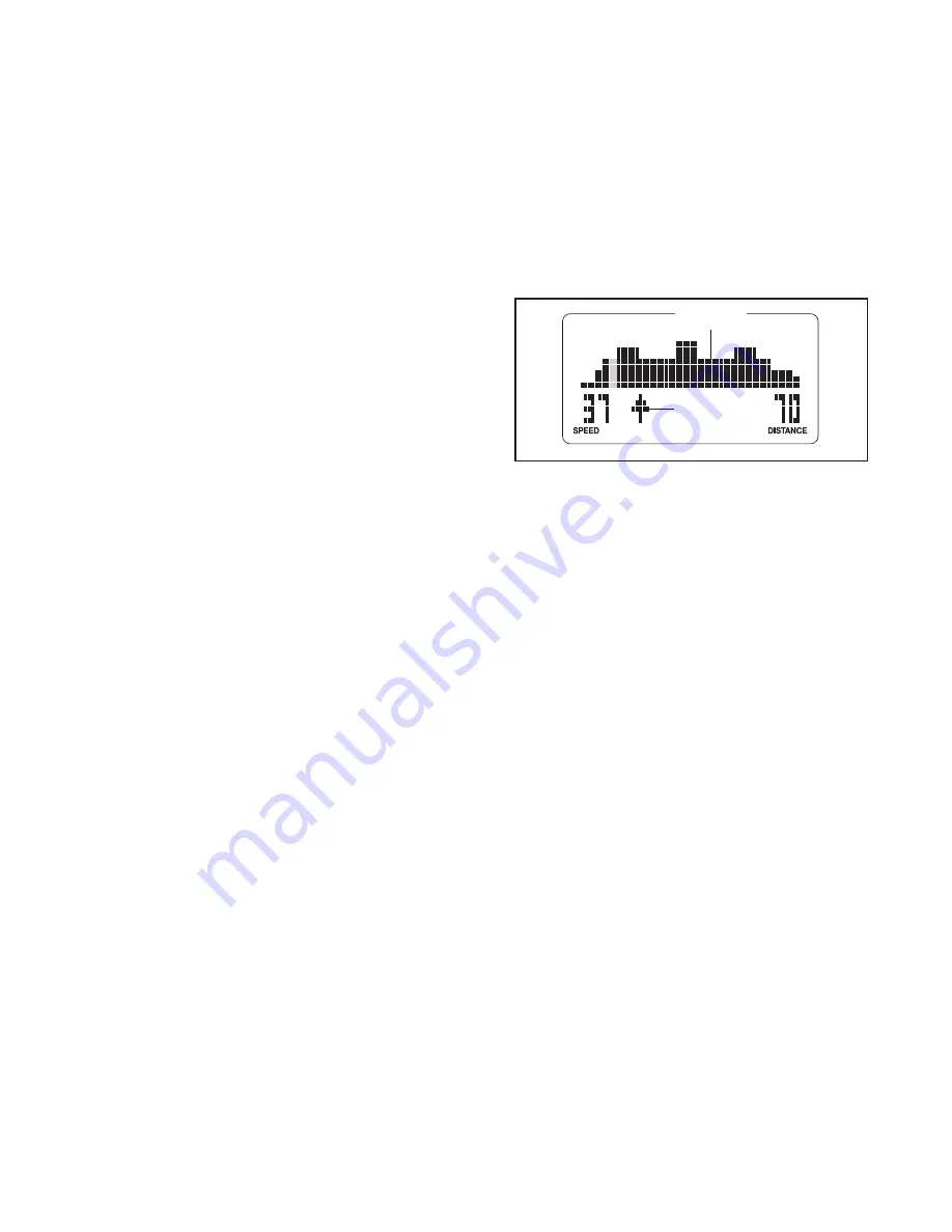
During the workout, the workout profile in the dis-

play will show your progress. The flashing column

of the profile represents the current segment of the

workout. The height of the flashing column indi-

cates the target heart rate setting for the current

segment. At the end of each segment of the work-

out, a series of tones will sound and the next seg-

ment of the profile will begin to flash.

During both workouts,

the console will regularly

compare your heart rate to the target heart rate

setting for the current segment of the workout. If

your heart rate is too far below or above the target

heart rate setting, the resistance of the pedals will

automatically increase or decrease to bring your

heart rate closer to the target heart rate setting.

Each time the resistance changes, the resistance

setting will appear in the display for a few seconds

to alert you.

While you exercise, you will be prompted to main-

tain a constant pedaling pace. If an upward-point-

ing arrow appears in the display (see the drawing

above), increase your pace. If a downward-point-

ing arrow appears, decrease your pace. When no

arrow appears, maintain your current pace.

Profile

Arrow

Summary of Contents for NTEL00807.0

Page 1: ...providing complete customer satisfaction If you have questions or if parts are damaged or missing PLEASE DO NOT CONTACT THE STORE please contact Customer Care IMPORTANT You must note the product mode...

Page 2: ...DERING REPLACEMENT PARTS Back Cover LIMITED WARRANTY Back Cover 2 NordicTrack is a registered trademark of ICON IP Inc WARNING DECAL PLACEMENT The warning decals shown here have been applied in the lo...

Page 3: ...ercise clothes when exercising do not wear loose clothes that could become caught on your elliptical exer ciser Always wear athletic shoes for foot protection 9 Hold the handgrip pulse sensor or the u...

Page 4: ...ual carefully before you use the elliptical exerciser If you have ques tions after reading this manual please see the front cover of this manual To help us assist you note the product model number and...

Page 5: ...the PART LIST near the end of this manual The number following the parentheses is the quantity needed for assembly Note Some small parts may have been preassembled If a part is not in the hardware ki...

Page 6: ...e another person lifts the Folding Frame 2 attach the Rear Stabilizer to the Folding Frame with two M10 x 80mm Patch Screws 93 and two M10 Split Washers 99 3 92 37 99 99 40 33 2 93 3 1 36 92 1 2 1 See...

Page 7: ...arnesses 64 65 during this step While another person holds the Upright 10 near the Frame 1 connect the Upper Wire Harness 65 to the Lower Wire Harness 64 Then insert the Upright 10 into the Frame 1 At...

Page 8: ...ase to the Upper Body Axle 71 Insert the Upper Body Axle into the Upright 10 Apply a small amount of grease to a Wave Washer 80 Slide the Wave Washer onto the left end of the Upper Body Axle 71 Identi...

Page 9: ...eries into the Console If you do not do this the console displays or other electronic components may become damaged Press the tabs on the battery covers and remove the battery covers Next insert four...

Page 10: ...arness 65 Next connect the console pulse wire to the Pulse Sensor Wire 111 Then connect the console ground wire to the Ground Wire 112 Insert the excess wire into the Upright Attach the Console 11 to...

Page 11: ...to the Link Arm with three M8 x 45mm Patch Screws 90 three M8 Split Washers 97 and three M8 x 23mm Washers 31 Repeat this step for the Left Pedal not shown and the other Link Arm not shown 14 35 31 3...

Page 12: ...g 72 Make sure that the flat side of the Upper Body Leg Spacer is facing out ward At the same time slide the right Pedal Arm 32 onto the Right Upper Body Leg 72 and insert the right Link Arm 30 into t...

Page 13: ...liptical exerciser hold the handle press the latch button and then lower the frame to the floor HOW TO MOVE THE ELLIPTICAL EXERCISER To move the elliptical exerciser first fold it as described at the...

Page 14: ...free wheel the pedals will continue to move until the flywheel stops When the pedals are stationary step off the higher pedal first Then step off the lower pedal HOW TO ADJUST THE STRIDE OF THE ELLIPT...

Page 15: ...tures the new iFIT Interactive Workout System The iFIT Interactive Workout System enables the console to accept iFIT cards containing workouts designed to help you achieve specific fitness goals For e...

Page 16: ...y will show your pedaling speed in revolutions per minute rpm The upper right corner of the display will show your heart rate when you use the handgrip pulse sensor see step 5 on page 17 The lower rig...

Page 17: ...ptimal performance clean the metal contacts using a soft cloth never use alcohol abrasives or chemicals to clean the contacts 6 Turn on the fan if desired The fan has high low and auto speed settings...

Page 18: ...rcise you will be prompted to keep your pedaling pace near the target pace setting for the cur rent segment When an upward pointing arrow appears in the display increase your pace When a downward poin...

Page 19: ...ndgrip pulse sensor keep your hands on the metal contacts for at least 30 seconds 5 Begin pedaling to start the workout Heart rate workout 1 is divided into 40 one minute segments Note For a shorter w...

Page 20: ...rn on the fan if desired See step 6 on page 17 8 When you are finished exercising the console will turn off automatically See step 7 on page 17 HOW TO USE AN IFIT WORKOUT 1 Press any button on the con...

Page 21: ...tion of the Side Shields 14 15 until the Discs 12 no longer rub against them and then tighten the Bolt Sets 88 and the M4 x 19mm Screws 81 HOW TO ADJUST THE BELT If the pedals slip while you are pedal...

Page 22: ...ur goal is to strengthen your cardiovascular system you must perform aerobic exercise which is activity that requires large amounts of oxygen for prolonged periods of time For aerobic exercise adjust...

Page 23: ...lles Stretch With one leg in front of the other reach forward and place your hands against a wall Keep your back leg straight and your back foot flat on the floor Bend your front leg lean forward and...

Page 24: ...y Mechanism 45 2 Link Arm Bracket 46 2 Adjustment Arm 47 1 Idler 48 1 Idler Pulley 49 1 Resistance Motor 50 1 Reed Switch Wire 51 1 Clamp 52 2 Adjustment Knob 53 2 Pivot Arm Bushing 54 4 Link Snap Rin...

Page 25: ...ssembly 103 4 Large Snap Ring 104 2 M10 x 58mm Shoulder Bolt 105 2 M8 x 23mm Shoulder Patch Screw 106 2 M8 Washer 107 2 M8 x 32mm Washer 108 1 Upper Handlebar Cover 109 1 Lower Handlebar Cover 110 2 P...

Page 26: ...66 67 67 68 68 7 7 8 9 16 16 93 91 82 92 86 31 80 92 92 92 84 97 97 92 83 105 89 73 77 92 92 91 96 99 5 83 83 83 31 97 31 97 90 106 22 24 26 27 32 34 5 66 67 67 71 7 7 8 9 73 92 86 31 80 92 84 97 84 9...

Page 27: ...46 101 45 104 94 31 2 3 16 16 12 13 30 52 117 53 55 56 57 58 6 64 62 63 74 87 87 114 114 87 39 116 99 99 76 93 107 44 47 48 49 50 51 115 45 103 104 94 18 42 42 43 54 54 79 103 46 101 31 1 37 36 65 69...

Page 28: ...e for a mini mal trip charge This warranty does not extend to any product or damage to a product caused by or attrib utable to freight damage abuse misuse improper or abnormal usage or repairs not pro...

Reviews: