
15
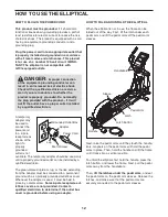
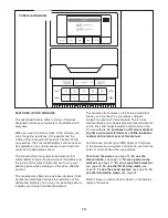
HOW TO TURN ON THE POWER
IMPORTANT: If the elliptical has been exposed to
cold temperatures, allow it to warm to room tem-
perature before turning on the power. If you do not
do this, you may damage the console displays or
other electrical components.
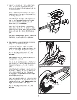
Plug in the power cord (see
HOW TO PLUG IN THE
POWER CORD on page
12). Next, locate the power
switch on the frame near
the power cord. Make sure
that the power switch is in
the reset position.
The display will then light and the console will be
ready for use.
Note: When you turn on the power for the first
time, the ramp will calibrate automatically.
The
ramp will move upward and downward as it calibrates.
When the ramp stops moving, the ramp is calibrated.
IMPORTANT: If the ramp does not calibrate auto-
matically, see HOW TO CALIBRATE THE RAMP on
page 20 and manually calibrate the ramp.
HOW TO USE THE MANUAL MODE
1. Begin pedaling or press any button on the
console to turn on the console.
See HOW TO TURN ON THE POWER above.
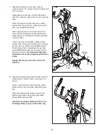
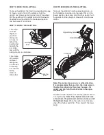
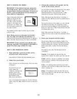
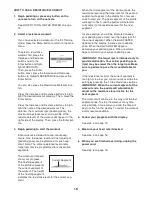
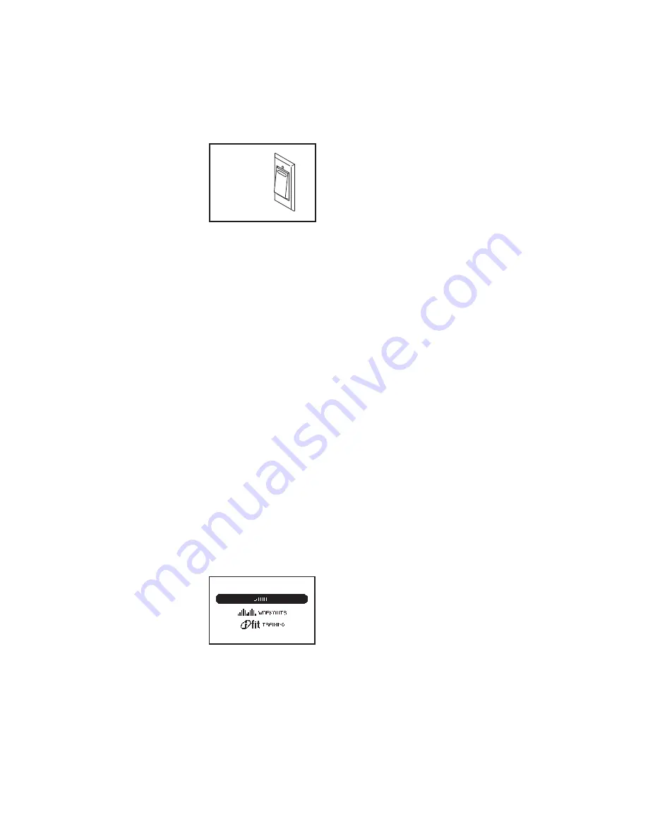
2. Select the manual mode.
Each time you turn on the console, the main menu
will appear.
To select the manual
mode, press the
Increase and Decrease
buttons next to the
Enter button and high-
light START. Then,
press the Enter button.
If you have selected a workout or the iFit Training
mode, press the Menu button to return to the main
menu.
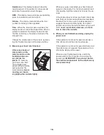
3. Change the resistance of the pedals and the
incline of the ramp as desired.
As you pedal, change the resistance of the pedals
by pressing one of the numbered 1 Step
Resistance buttons or by pressing the 1 Step
Resistance Increase and Decrease buttons.
Note: After you press the buttons, it will take a
moment for the pedals to reach the selected resis-
tance level.
To vary the motion of the pedals, you can change
the incline of the ramp. To change the incline,
press one of the numbered 1 Step Power Ramp
buttons or press the 1 Step Power Ramp Increase
and Decrease buttons.
Note: After you press the buttons, it will take a
moment for the ramp to reach the selected incline
level.
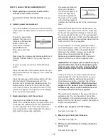
4. Follow your progress with the display.
The console offers several display modes. The
display mode that you select will determine which
workout information is shown. Press the Display
button repeatedly to select the desired display
mode.
The display can show the following workout
information:
Calories
—This display mode will show the
approximate number of calories you have burned.
Profile
—When a workout is selected, this display
mode will show a profile of the resistance levels
for the workout.
Pulse
—This display mode will show your heart
rate when you use the handgrip pulse sensor (see
step 5 on page 16).
Ramp
—This display mode will show the incline
level of the ramp for a few seconds each time the
ramp incline changes.
Reset
Position


