background image

23

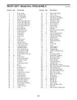
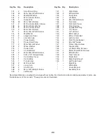
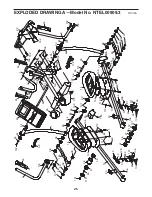
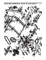
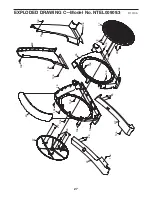
PART LIST—Model No. NTEL00909.3

R1010A

1

1

Main Frame

2

1

Folding Frame

3

1

Front Stabilizer

4

1

Rear Stabilizer

5

1

Upright

6

1

Right Upper Body Leg

7

1

Left Upper Body Leg

8

1

Right Upper Body Arm

9

1

Left Upper Body Arm

10

1

Pivot Frame

11

1

Motor Bracket

12

1

Right Pedal Arm

13

1

Left Pedal Arm

14

1

Right Pedal

15

1

Left Pedal

16

2

Wheel Cap

17

2

Disc

18

1

Right Shield

19

1

Left Shield

20

1

Access Cover

21

1

Right Frame Cover

22

1

Left Frame Cover

23

1

Lift Motor Cover

24

1

Left Ramp Cover

25

1

Rear Upright Cover

26

1

Water Bottle Holder

27

1

Right Ramp Cover

28

1

Right Pedal Arm Cover

29

16

Mount

30

2

Latch Cover

31

1

Motor Reed Switch

32

2

Pedal Arm Roller

33

1

Console

34

2

Pulse Sensor/Wire

35

2

Grip

36

2

Wheel

37

2

Stabilizer Cap

38

1

Drive Belt

39

2

Crank Arm

40

1

Left Pedal Arm Cover

41

3

Leveling Foot

42

1

Latch Bracket

43

1

Right Link Arm

44

2

Inner Sleeve Bushing

45

4

M8 x 35mm Screw

46

2

Pedal Arm Sleeve

47

2

Outer Sleeve Bushing

48

1

Upright Axle

49

2

Latch Housing

50

2

Latch

51

2

Large Latch Spring

52

2

Latch Insert

53

4

Long Latch Spring

54

4

Leg Bearing Assembly

55

2

Cushion Cylinder

56

6

Small Axle Cover

57

2

Upright Bushing

58

12

Small Bushing

59

1

Audio Cable

60

1

Wire Harness

61

1

Flywheel

62

4

M6 x 50mm Patch Screw

63

1

Frame Axle

64

10

Front Frame Bushing

65

1

Latch Bracket Axle

66

1

Latch Bracket Spring

67

1

Latch Button

68

1

Button Housing

69

1

Reed Switch/Wire

70

1

Clamp

71

1

Crank Hub

72

1

Crank

73

1

Crank Spacer

74

1

Large Pulley

75

2

Pulley Magnet

76

2

Folding Frame Bearing

77

1

Idler

78

1

Resistance Motor

79

1

Adjustment Assembly

80

1

Resistance Wheel

81

1

Adjustment Lock

82

1

Motor Bracket

83

1

C-magnet Bracket

84

1

Flywheel Axle

85

1

Belt Adjustment Screw

86

8

M8 x 28mm Shoulder Patch Screw

87

4

Large Snap Ring

88

1

C-magnet Bracket Bolt

89

4

Resistance Motor Screw

90

1

M5 x 7mm Screw

91

1

M3.5 x 12mm Screw

92

1

M6 Locknut

93

1

Cylinder Axle

94

2

M8 Jam Nut

95

12

M8 Washer

96

1

Idler Washer

97

1

Pivot Screw

98

2

Motor Bracket Screw

99

1

Idler Bolt

100

4

M10 x 95mm Patch Screw

Key No. Qty.

Description

Key No. Qty.

Description

Summary of Contents for NTEL00909.0

Page 1: ...ssing DO NOT CONTACT THE STORE please contact Customer Care IMPORTANT Please register this product see the limited warranty on the back cover of this manual before contacting Customer Care CALL TOLL F...

Page 2: ...DRAWING 25 ORDERING REPLACEMENT PARTS Back Cover LIMITED WARRANTY Back Cover WARNING DECAL PLACEMENT 2 NordicTrack is a registered trademark of ICON IP Inc This drawing shows the location s of the war...

Page 3: ...6 m on each side To protect the floor or carpet from damage place a mat under the elliptical 7 Inspect and properly tighten all parts regu larly Replace any worn parts immediately 8 Keep children und...

Page 4: ...see the front cover of this manual To help us assist you note the product model number and serial number before contacting us The model number and the location of the serial number decal are shown on...

Page 5: ...rawings below to identify small parts The number in parentheses below each drawing is the key number of the part from the PART LIST near the end of this manual The number fol lowing the parentheses is...

Page 6: ...the Rear Stabilizer 4 press the Latch Button 67 and unfold the elliptical so that the Rear Stabilizer is resting on the floor 1 2 Orient the Front Stabilizer 3 so that the small welded tubes are faci...

Page 7: ...ing the Wire Harness 60 3 Orient the Upright 5 as shown Have a second person hold the Upright near the Main Frame 1 Locate the wire tie in the Upright 5 Tie the lower end of the wire tie to the Wire H...

Page 8: ...l Arm 12 Press the Right Pedal Arm onto the Pedal Arm Sleeve 46 Make sure that the Right Pedal Arm latches into place Repeat this step on the other side of the elliptical 5 Identify the Right Pedal 14...

Page 9: ...ing a second hex key tighten another M8 x 16mm Patch Screw 102 a Small Axle Cover 56 and an M8 Washer 95 into the other end of the Link Arm Axle Tip Avoid damaging the Small Axle Cover when tightening...

Page 10: ...upward into the Console 33 Insert the Wire Harness 60 downward into the Upright 5 Tip Avoid pinching the wires Attach the Console 33 to the Upright 5 with four M4 x 16mm Screws 106 See step 3 Tighten...

Page 11: ...me Covers 21 not shown Then press the tabs on the Lift Motor Cover 23 into the Rear Upright Cover 25 23 25 12 Make sure that all parts of the elliptical are properly tightened Note Some hardware may b...

Page 12: ...qualified electrician to determine if the outlet box cover is grounded before using an adapter HOW TO FOLD AND UNFOLD THE ELLIPTICAL When the elliptical is not in use the frame can be folded out of th...

Page 13: ...motion is eliminated HOW TO EXERCISE ON THE ELLIPTICAL To mount the elliptical hold the upper body arms or the handlebars and step onto the pedal that is in the lowest position Next step onto the oth...

Page 14: ...rompts you to vary your pedaling pace as it guides you through an effective workout The console also features an iFit training mode that allows you to connect to your wireless network through an optio...

Page 15: ...the Menu button to return to the main menu 3 Change the resistance of the pedals and the incline of the ramp as desired As you pedal change the resistance of the pedals by pressing one of the numbere...

Page 16: ...al contacts Avoid moving your hands or gripping the contacts tightly When your pulse is detected your heart rate will appear in the display For the most accurate heart rate reading hold the contacts f...

Page 17: ...tes the resistance level for the current seg ment When the first segment of the workout ends the resistance level ramp incline and the target rpm for the second segment will appear in the display for...

Page 18: ...flashing segment indicates the resistance level for the current seg ment When the first segment of the workout ends the resistance level and the target rpm for the second segment will appear in the di...

Page 19: ...the jack on the side of the console and into a jack on your MP3 player or CD player make sure that the audio cable is fully plugged in Next press the play button on your MP3 player or CD player Adjust...

Page 20: ...s the One Step Power Ramp Increase or Decrease button to calibrate the ramp The ramp will move upward and downward as it calibrates When the ramp stops moving the ramp is calibrated Then press the Pow...

Page 21: ...Pedal Arm off the left Pedal Arm Sleeve 46 Next remove the indicated M8 x 25mm Patch Screw 121 Large Axle Cover 113 M8 Washer 95 and Pedal Arm Sleeve 46 Using a flat screwdriver care fully pry the le...

Page 22: ...your goal is to strengthen your cardiovascular system you must perform aerobic exercise which is activity that requires large amounts of oxygen for prolonged periods of time For aerobic exercise adju...

Page 23: ...leeve Bushing 48 1 Upright Axle 49 2 Latch Housing 50 2 Latch 51 2 Large Latch Spring 52 2 Latch Insert 53 4 Long Latch Spring 54 4 Leg Bearing Assembly 55 2 Cushion Cylinder 56 6 Small Axle Cover 57...

Page 24: ...x 12mm Bright Screw 130 1 Left Ramp 131 1 Right Ramp 132 2 M10 Bolt Set 133 1 Ramp Axle 134 1 Lift Motor 135 2 M4 x 38mm Screw 136 2 Pivot Axle 137 2 Pivot Axle Cover 138 2 Pivot Bushing 139 2 Cylind...

Page 25: ...95 127 106 49 51 52 50 40 30 95 102 121 95 35 9 7 102 103 102 103 25 105 56 144 58 58 58 58 58 13 113 47 44 46 112 112 111 62 62 32 111 112 112 12 32 101 62 112 113 44 46 47 58 58 128 43 102 114 56 9...

Page 26: ...106 106 70 69 125 120 124 123 146 106 129 64 108 107 64 63 108 95 72 39 86 100 119 147 107 38 61 115 116 2 37 4 37 122 39 130 133 64 1 64 41 16 100 36 36 126 3 126 16 142 143 134 41 41 64 93 132 64 60...

Page 27: ...27 EXPLODED DRAWING C Model No NTEL00909 3 R1010A 17 17 18 19 20 21 22 106 106 106 106 106 106 106 106 106 106 106 106 29 106 106 29 29 29 29 106 106 29 29 27 24...

Page 28: ...xtend to any damage to a product caused by or attributable to freight damage abuse misuse improper or abnormal usage or repairs not provided by an ICON authorized service center to products used for c...

Reviews: