background image

25

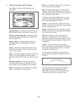
 HOW TO USE THE SOUND SYSTEM

To play music or audio books through the console 
sound system while you exercise, plug the included 
audio cable into the jack on the console and into a jack 
on your MP3 player or CD player; 

make sure that the 

audio cable is fully plugged in.


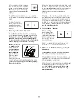
Next, press the play button 
on your MP3 player or CD 
player. Adjust the volume 
level using the volume 
increase and decrease 
buttons on the console or 
the volume control on your MP3 player or CD player. 

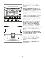
 HOW TO CHANGE CONSOLE SETTINGS

The console features a user mode that keeps track 
of elliptical information and allows you to personalize 
console settings.

To select the user mode, hold down the Fan increase 
button until the user mode information appears in the 
display.

The time display will show the total number of hours 
that the elliptical has been used. 

The distance display will show the total distance (in 
thousands of strides) that the pedals have moved. 

The lower section of the display will show the status 
of an iFit Live module. If a wireless iFit Live module 
is connected, the display will show the words WIFI 
MODULE. If a USB module is connected, the display 
will show the words USB/SD MODULE. If no module 
is connected, the display will show the words NO IFIT 
MODULE.

The matrix will show the selected unit of measure-
ment. To change the unit of measurement, press the 
Enter button repeatedly. To view distance in kilome-
ters, select METRIC. To view distance in miles, select 
ENGLISH.

Press the decrease button above the Enter button. 
The display will show the contrast level of the display. 
Press the Incline/Decline increase and decrease but-
tons to adjust the contrast level.

The following settings can be viewed and changed 
when an iFit Live module is connected:

Press the decrease button next to the Enter button to 
view the status of the personal trainer voice. To turn 
on or turn off the voice, press the Enter button. 

Press the decrease button next to the Enter button to 
view the default menu. The default menu will appear 
when you turn on the power. Press the Enter button 
repeatedly to select the manual main screen or the iFit 
Live main screen as the default menu.

Press the decrease button next to the Enter button to 
view the next setting. Then, press the Enter button to 
check the connection status of an iFit Live module. 

If a wireless iFit Live module is connected, the display 
will show the words WIFI STATUS and the signal 
strength. If a USB module is connected, the display 
will show the words USB STATUS. If the module is not 
detected, the display will show the words NO 
MODULE DETECTED.

Press the decrease button next to the Enter button to 
view the next setting. To send and receive workouts, 
workout logs, and updates using a wireless iFit Live 
module, press the Enter button. When the process is 

 nished, the words TRANSFERS DONE will appear in 

the display.

To exit the user mode, press the Fan increase button.

Summary of Contents for NTEL01310.4

Page 1: ...ace above for reference USER S MANUAL www nordictrack com QUESTIONS If you have questions or if parts are damaged or missing DO NOT CONTACT THE STORE please contact Customer Care IMPORTANT Please regi...

Page 2: ...Note The decal s may not be shown at actual size NORDICTRACK is a registered trademark of ICON IP Inc WARNING DECAL PLACEMENT 2 IMPORTANT PRECAUTIONS 3 BEFORE YOU BEGIN 4 PART IDENTIFICATION CHART 5 A...

Page 3: ...ical and 2 ft 0 6 m on each side To protect the floor or carpet from dam age place a mat under the elliptical 7 Inspect and properly tighten all parts regu larly Replace any worn parts immediately 8 K...

Page 4: ...tions after reading this manual please see the front cover of this manual To help us assist you note the product model number and serial number before contacting us The model number and the location o...

Page 5: ...6 x 10mm Screw 121 8 8 x 3 4 Screw 123 11 Use the drawings below to identify small parts used in assembly The number in parentheses below each draw ing is the key number of the part from the PART LIST...

Page 6: ...Orient the Front Stabilizer Cover 8 as shown Press the Mounts 117 on the Front Stabilizer Cover 8 into the Frame 1 Then press the Front Stabilizer Cover into place 1 2 6 1 1 84 8 117 Assembly requires...

Page 7: ...5mm Screws 119 Then remove and discard the shipping bracket not shown 119 Welded Tubes 4 1 2 117 4 Orient the Rear Stabilizer Cover 2 as shown Press the Mounts 117 on the Rear Stabilizer Cover 2 into...

Page 8: ...4 on the Frame 1 Attach the Upright 4 with four M8 x 19mm Screws 82 and four M8 Star Washers 122 6 Avoid pinching the Main Wire 110 1 82 4 122 110 7 56 75 7 Orient the Lower Upright Cover 56 as shown...

Page 9: ...vot Axle 35 and to two Wave Washers 95 Insert the Pivot Axle 35 through the Upright 4 and then center it Tip It may be helpful to use a rubber mallet Identify the Right Upper Body Arm 61 which is mark...

Page 10: ...10 120 120 98 98 35 Avoid pinching the wires 11 Identify the Right Pedal 49 and the Right Pedal Arm 58 which are marked with Right stickers and orient them as shown Attach the Right Pedal 49 to the R...

Page 11: ...to a Wave Washer 95 Orient an Upper Body Leg 46 as shown Note For clarity the Right Upper Body Arm 61 is not shown in this step Insert the Pedal Arm Axle 36 through the Right Pedal Arm 58 the Wave Wa...

Page 12: ...knuts 102 Make sure that the Locknuts are in the hexagonal holes Repeat this step for the Left Upper Body Arm 47 and the other Upper Body Leg 46 15 68 55 123 123 15 Tip Avoid pinching the wires Attach...

Page 13: ...rol Wires 41 48 Insert the excess wire into the Upright 4 or into the Console 7 7 4 16 Insert the Right Control Wire 41 into the hole in the right side of the Upright 4 and pull it upward out of the t...

Page 14: ...4 Screws 123 20 19 Identify the Right Outer Cover 67 which is marked with a Right sticker and orient it as shown Attach the Right Outer Cover 67 to the Right Inner Cover 68 and the right Upper Body Le...

Page 15: ...e Extra parts may be left over Place a mat beneath the elliptical to protect the floor 21 Orient the Front Upright Cover 91 as shown Press the Front Upright Cover 91 into the Rear Upright Cover 80 Att...

Page 16: ...tures above 122 F 50 C or below 14 F 10 C Do not excessively bend or stretch the sensor when using or storing the heart rate monitor To clean the sensor use a damp cloth and a small amount of mild soa...

Page 17: ...ng from the adapter must be connected with a metal screw to a permanent ground such as a properly grounded outlet box cover Some 2 pole receptacle outlet box covers are not grounded Before using an ad...

Page 18: ...d step onto the pedal that is in the lower position Then step onto the other pedal Push the pedals until they begin to move with a continuous motion Note The crank arms can turn in either direction It...

Page 19: ...ou through an effective workout The console features revolutionary iFit Live technol ogy that enables the console to communicate with your wireless network through an optional iFit Live module With th...

Page 20: ...SE THE MANUAL MODE 1 Begin pedaling or press any button on the console to turn on the console See HOW TO TURN ON THE POWER at the left 2 Select the manual mode Press the Manual Control button on the c...

Page 21: ...n the manual mode is selected this display mode will show the elapsed time When a workout is selected this display mode will show the time remaining in the workout The matrix offers several display ta...

Page 22: ...ach time your heart beats one or two dashes will appear and then your heart rate will be shown For the most accurate heart rate reading hold the contacts for at least 15 seconds If the display does no...

Page 23: ...profile will begin to flash If a different resis tance level ramp incline level and or target rpm is programmed for the next segment the resistance level ramp incline level and or target rpm will appe...

Page 24: ...World Tour but ton or the Event Training button to download the next workout of that type in your schedule Press the Compete button to compete in a race that you have previously scheduled For more in...

Page 25: ...Enter button repeatedly To view distance in kilome ters select METRIC To view distance in miles select ENGLISH Press the decrease button above the Enter button The display will show the contrast leve...

Page 26: ...equipment does cause harmful interference to radio or television reception which can be determined by turning the equipment off and on try to correct the interference by one or more of the following m...

Page 27: ...to calibrate the ramp The ramp will move upward and downward as it calibrates When the ramp stops moving the ramp is calibrated Then press the Quads Tibialis Core button repeatedly to exit the calibr...

Page 28: ...m the right disc the front stabilizer cover the shield cover and the lower upright cover HOW TO ADJUST THE REED SWITCH If the console does not display correct feedback the reed switch should be adjust...

Page 29: ...c Exercise If your goal is to strengthen your cardiovascular system you must perform aerobic exercise which is activity that requires large amounts of oxygen for prolonged periods of time For aerobic...

Page 30: ...lles Stretch With one leg in front of the other reach forward and place your hands against a wall Keep your back leg straight and your back foot flat on the floor Bend your front leg lean forward and...

Page 31: ...2 Roller 52 2 Pedal Arm Cap 53 6 Axle Cover 54 1 Left Outer Cover 55 1 Left Inner Cover 56 1 Lower Upright Cover 57 4 Roller Arm Bushing 58 1 Right Pedal Arm 59 8 Axle Bushing 60 2 Crank Arm Cover 61...

Page 32: ...rew 122 4 M8 Star Washer 123 11 8 x 3 4 Screw 124 6 8 x 1 2 Screw 125 2 M6 x 12mm Screw 126 4 M4 x 75mm Screw 127 14 M4 x 22mm Screw 128 2 M4 x 16mm Screw 129 2 M8 x 23mm Washer 130 1 Heart Rate Monit...

Page 33: ...53 98 120 46 57 21 12 51 33 57 81 98 120 133 53 98 37 133 104 104 71 128 60 76 104 104 104 104 73 104 104 104 80 123 35 91 55 70 104 75 56 48 47 54 120 123 98 70 96 102 52 120 95 104 104 95 123 126 12...

Page 34: ...2 92 119 117 5 13 92 116 34 92 6 116 34 8 99 84 16 17 1 117 2 9 3 11 10 15 40 83 127 127 127 115 117 115 117 117 115 125 32 32 97 117 85 86 78 85 86 78 7 124 124 19 43 43 99 99 106 120 98 120 98 110 1...

Page 35: ...87 120 121 52 57 21 57 51 98 81 120 33 104 104 74 104 77 127 127 127 104 60 128 104 104 104 104 123 68 70 67 120 98 70 102 123 49 133 45 133 53 98 120 96 46 41 71 61 95 104 104 104 126 95 127 127 EXP...

Page 36: ...not extend to freight damage to the product This warranty will automatically be voided if the product is used as a store display model if the product is purchased or transported outside the USA if all...

Reviews: